GOST 30971-2012 INSTALLATION JOINTS OF JOINTS OF WINDOW UNITS TO WALL OPENINGS
General Specifications
Erection to joints of window assemblies adjoined to wall openings
Date of introduction 2014-01-01
Preface
The goals, basic principles and basic procedure for carrying out work on interstate standardization are established by GOST 1.0-92 “Interstate standardization system. Basic provisions” and GOST 1.2-2009 “Interstate standardization system. Interstate standards, rules and recommendations for interstate standardization. Rules for development, adoption, application, updating and cancellation"
Standard information
1 DEVELOPED by the Limited Liability Company NIUPTS "Interregional Window Institute" (NIUPTs "Interregional Window Institute") with the participation of the Institution "Research Institute of Building Physics of the Russian Academy of Architecture and Construction Sciences" (NIISF RAASN), State Unitary Enterprise "Research Institute of Moscow Construction "(SUE "NIIMosstroy")
2 INTRODUCED by the Technical Committee for Standardization TC 465 “Construction”
3 ADOPTED by the Interstate Scientific and Technical Commission for Standardization, Technical Regulation and Conformity Assessment in Construction (MNTKS) (Minutes dated June 14, 2012 N 40)
The following voted for the adoption of the standard:
Short name of the country according to MK (ISO 3166)004-97
Country code according to MK (ISO 3166) 004-97
Abbreviated name of the state construction management body
Ministry of Regional Development
Agency for Construction and Architecture under the Government
4 By Order of the Federal Agency for Technical Regulation and Metrology dated December 27, 2012 N 1983-st, the interstate standard GOST 30971-2012 was put into effect as the national standard of the Russian Federation on January 1, 2014.
5 INSTEAD GOST 30971-2002
Units for sealing joints between hollow core slabs (download drawing in dwg format)
In series 2.140.1-1 issue. 1 provides solutions for sealing joints between hollow-core floor slabs. Although these are simple, but important components, they must be shown on the drawings of the prefabricated floor. For good performance of the slabs, for reliable adhesion, you need to completely fill the seams with cement mortar, as shown in node 1. If this is not done, over time, under different loads, the slabs will bend differently, and this will be clearly and unsightly visible on the ceiling in the room. If the seams between the slabs are filled with high quality, such an aesthetic defect can be avoided.
Introduction
This standard is intended for use when performing work on filling installation gaps between the surface of a wall opening and the frame planes of a window (door) block, as well as when designing junctions of window and door blocks.
This standard was developed on the basis of a technical analysis of many years of operation of window (door) units in various climatic conditions on the territory of the Russian Federation and the countries of the Commonwealth of Independent States.
This standard is aimed at improving the comfort of living, increasing durability and energy efficiency in construction in terms of increasing the requirements for the heat-shielding characteristics of the junction points of window (door) units.
The requirements of this standard are intended for use by organizations operating in the field of construction and design, regardless of their form of ownership and nationality.
Monolithic section between the slab and the wall (download drawing in dwg format)
The monolithic section between the slab and the wall is a fairly common design. Its reinforcement must be done according to calculation - the workers are curved rods resting on one side on the slab, on the other on the wall.
The design of such monolithic sections is described in detail in the article “Monolithic section between a prefabricated slab and a wall.”
Connections between window blocks and wall openings. Part 2
posted: February 05, 2020
Connections of window blocks to openings
in three-layer walls
The three-layer wall system itself with a facing layer of brick and effective insulation raises a lot of controversy and questions, and yet remains one of the most popular solutions for the facades of residential and public buildings.
The junction of window blocks is one of the “pain points” of this solution for external walls. The optimal placement of a window block in the thickness of the insulation from the point of view of heating engineering is not convenient and optimal from the point of view of ease of work.
Often, various sources suggest performing this unit with an antiseptic board covering the effective insulation in the openings. Installing a board is an inconvenient process for installers; in addition, there is a question about the survivability of the board in such a unit (“will the board rot?”). On the other hand, the contact between the foam insulation of the installation seam and the mineral wool insulation of the wall is also not a reliable solution: in a three-layer wall, it is permissible to use low-density thermal insulation, and most often it is this kind of insulation that is used; with constant movement of the mounting seam (temperature expansion, wind pressure, etc.), the mounting foam will eventually fray the non-rigid insulation board at the junction, forming a void along the contour of the window block; such emptiness will become a “bridge of cold.”
There are no unambiguous requirements for the need to install a board covering the wall insulation in the opening. This decision is made when developing a specific node for a specific object.
Often the board is installed only in the upper junction of the window block and the wall opening. In the construction of multi-storey residential (and public) buildings with three-layer external walls, scaffolding is rarely used, so the masonry is carried out from the outside inwards (from the front mile inwards), flexible connections are installed in the front mile, using special clamps on them, providing a gap between the front mile and the insulation, the insulation is hung, and the inner mile is built last. With this installation method, the insulation is not additionally attached to the inner surface either mechanically or with glue. The board in the upper junction prevents the insulation from sagging. Various options for replacing the board in this unit are also practiced, for example, with metal brackets with a pitch of 300 mm.
When developing units for connecting windows to openings in three-layer walls with flammable insulation (for example, extruded polystyrene foam in basement walls), it is important not to forget about the fire protection framing of the opening with non-combustible insulation.
Connections of window blocks to openings
in walls with external thermal insulation
In walls with external thermal insulation and a finishing coating of thin-layer plaster, when polystyrene foam boards are used as insulation, fire-resistant cuts made of non-combustible insulation are provided, including along the perimeter of the openings.
For walls with a suspended ventilated facade, there are also requirements for fireproof framing of openings. All NVF systems have their own solutions for fire ducts for framing openings. The main types are discussed, for example, in STO NOSTROY 2.14.67-2012 (section 6.2). When developing connections between window blocks and wall openings with a suspended ventilated façade, it is permissible not to show fireproof casings in the AR section, because the project (section) of the NVF will be developed separately, and fire ducts will be adopted depending on the choice of system. And in the AR section there should be a fundamental decision on the installation location of the window unit and the solution to the installation seam.
Bibliography
Source
Monolithic section between two slabs 150 mm wide (download drawing in dwg format)
The drawing shows a solution for constructing a monolithic section between two hollow-core floor slabs. The width of the area is 150 mm. This is a small gap between the slabs, so it is reinforced with thin reinforcement - a smooth six. A trough-shaped rod is placed on the slabs and holds the longitudinal reinforcement. The structure of such a monolithic section is described in detail in the article.
Attaching window blocks to the opening
According to paragraph B.5.3 of GOST 30971-2012, the choice of fastening elements and the distance between them along the contour of the opening, as well as the depth of embedding in the wall, are established in the working documentation based on calculations depending on the area and weight of the window product, the design of the wall opening, and the strength of the wall material , values of wind and other operational loads.
The minimum distances between fasteners should not exceed for:
The distance from the inner corner of the box to the fastening element is 150-180 mm; from the impost connection unit to the fastening element - 120-180 mm.
The minimum distances between fastening elements should not exceed those indicated in Table D.1 of GOST 30971-2012:
Table D.1 GOST 30971-2012
Distances between fasteners
Distance between fasteners, mm
— PVC profiles white
- colored PVC profiles
In accordance with paragraph B.5.4 of GOST 30971-2012, to transfer loads acting in the plane of the window block to the supporting building structure, support (bearing) pads made of polymer materials with a hardness of at least 80 units are used. Shore A or preservative-impregnated hardwood. The number and location of support blocks are determined in the working or technological documentation. The recommended block length should be 100-120 mm. The support blocks are installed after attaching the window block to the wall opening with fasteners.
The installation wedges are removed before installing the insulating layer of the assembly seam. When installing window blocks, it is allowed to use support blocks, which, after fastening, are turned from the installation position to the working position; their installation sites are filled with insulating material from the outside and inside (clause G.1.2 of GOST 30971-2012).
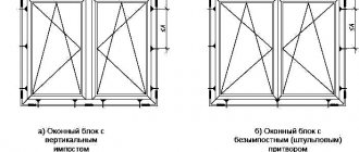
Examples of the location of the mounting points of the frame and support (bearing) blocks and fasteners when installing a window unit in accordance with Appendix G of GOST 30971-2012 are presented in the figures below:
Examples of the location of support (load-bearing) pads and fasteners
Examples of the location of support (load-bearing) blocks and fasteners in single-leaf window units
Project
House project 128 m2 (AR)
Attention!
When you buy a brick for your home, you receive a project with all the drawings (AP) for free! Two-story house 128 m2 with two entrance groups. Project K_031701.
Wall structure with a total thickness of 630 mm Ordinary solid brick 380 mm Effective insulation 100 mm Ventilation gap 30 mm Facing brick 120 mm
Internal load-bearing brick walls 380 mm Internal brick partitions 120 mm Roof: combined pitched truss structure Base: ordinary ceramic brick M125 with cladding
The house on the 1st floor has a staircase, a vestibule with a wardrobe, a corridor, a kitchen, a large living-dining room with access to the veranda and garden, a bathroom, and a technical room. On the 2nd floor there is a hall, 3 living rooms, one of them with a loggia, and a bathroom.
Number of bricks for the whole house: 50 180 pcs. Amount of cement: 15 tons. Red facing bricks 9,424 pcs. Yellow facing bricks 4,864 pcs. Insulation Technoblock Standard 100 mm. 126 pcs. Insulation Technoblock Standard 50 mm. 14 pcs.
By providing UfaStroyKeramika LLC (TIN 0273074210) with my contact information, in accordance with the requirements of the Federal Law of July 27, 2006 No. 152-FZ “On Personal Data,” I give unconditional consent to the processing of the personal data specified by me in this application, including, but not limited to, collection, systematization, accumulation, storage, clarification (updating, changing), use, depersonalization, destruction of personal data.
The processing of my personal data can be carried out in any way, both manual and automated.
This consent is valid for an indefinite period and can be revoked by me or my authorized representative by submitting a written statement to the location of UfaStroyKeramika LLC, no less than 30 days before the withdrawal of the relevant consent. If I receive my written application to withdraw this consent to the processing of personal data, UfaStroyKeramika LLC undertakes to stop processing it.
I acknowledge that by giving this consent, I am acting of my own free will and in my own best interests.
Arrangement of junction points for window blocks
The choice of a constructive solution for the junction of a window (door) block to the opening of an external wall is carried out at the stage of developing architectural and design solutions, taking into account the existing loads and is confirmed by appropriate calculations (clause 5.1.3 of GOST 30971-2012).
Examples of design solutions for junctions of window blocks to wall openings are given in Appendix B of GOST 30971-2012 and Appendix A of GOST R 52749-2007 (when using PSUL - insulating self-expanding vapor-permeable tapes).
Let us highlight the most common junction points of window blocks:
Figure B.1 GOST 30971-2012 - Unit for the top (side) connection of a window block to an opening with a quarter in a brick wall using PSUL tape without finishing the internal slope. 1 — insulating self-expanding vapor-permeable tape (PSUL); 2 - foam insulation; 3 - anchor plate; 4 - vapor barrier sealant
Figure B.2a GOST 30971-2012 - Unit for the upper (side) connection of a window block to an opening with a quarter in a brick wall using a vapor-permeable sealant with finishing of the internal slope with plaster mortar. 1 - vapor-permeable sealant; 2 - frame dowel; 3 — decorative plug; 4 - sealant; 5 - foam insulation; 6 - vapor barrier sealant; 7 - plaster mortar.
Figure B.4 GOST 30971-2012 - Unit for the upper (side) connection of a window block to an opening without a quarter in a single-layer concrete panel wall using sealants and finishing the internal slope with a moisture-resistant plasterboard sheet. 1 - vapor-permeable sealant; 2 - foam insulation; 3 - frame dowel; 4 - vapor-tight sealant or vapor barrier tape; 5 - PVC corner; 6 - polyethylene film; 7 - painted plasterboard sheet; 8 - PVC corner
Figure B.5 GOST 30971-2012 - Unit for the lower connection of a window block to an opening without a quarter in a single-layer concrete panel wall using a vapor barrier tape. 2 — noise-absorbing lining; 3 - foam insulation; 4 — support block; 5 - PVC corner; 6 - vapor-tight sealant or vapor barrier tape; 7 - support block; 8 - PVC window sill; 9 - plaster mortar Figure A.3 GOST R 52749-2007 - Unit for the side connection of a window block to an opening with a quarter of a layered brick wall with effective insulation and finishing of the internal slope with plaster mortar. 1 - foam insulation; 2 — insulating self-expanding vapor-permeable tape (PSUL); 3 - flexible anchor plate; 4 - sealant; 5 - vapor barrier tape; 6 - plaster layer of the internal slope (with a chamfer for the sealant layer); 7 - reinforcing mesh; 8 - dowel with locking screw
Figure A.4 GOST R 52749-2007 - Assembly of the lower connection of the window block, window sill and drain to the opening of a layered wall with effective insulation. 1 - window sill board; 2 - foam insulation; 3 - vapor barrier tape; 4 - flexible anchor plate; 5 — support block for the window sill board; 6 - plaster mortar; 7 - dowel with locking screw; 8 - liner made of antiseptic lumber or leveling layer of plaster mortar (recommended only for the lower unit); 9 — waterproofing, vapor-permeable tape; 10 — noise-absorbing gasket; 11 - drain; 12 — insulating self-expanding vapor-permeable tape (PSUL); 13 - thin layer of sealant
Source
Monolithic section between two slabs 980 mm wide (download drawing in dwg format)
Sometimes you have to make wide monolithic sections between the floor slabs. They must be calculated according to the current loads. The drawing shows a monolithic section with a width of 980 mm, supported by two hollow core slabs. The conditions for such a monolithic section (loads, principles of reinforcement, etc.) are described in detail in the article “Monolithic section between two prefabricated slabs”.