Many homeowners have to replace or install light switches. The most commonly used connection diagram is a single-key switch - one of the simplest schemes for turning on lamps or lamps. This article describes step by step how such a scheme is assembled.
Before starting any work related to electricity, the first thing you need to do is de-energize the electrical wiring - turn off the input circuit breaker, and also take measures to ensure that no one accidentally turns it on.
This is especially important if the electrical panel is located on a landing in a multi-story building or on the street.
To install and connect the switch you will need:
- – the switch itself;
- – distribution box;
- – connecting wires;
- – insulating PVC tape.
Connection diagram for a switch in a distribution box
Connecting a wire directly to a light fixture or switch is quite simple - it doesn't require any explanation.
This article will discuss how to connect wires from a lamp, electrical panel and switch in one junction box.
Once again we would like to remind you that all work on connecting wires in the distribution box, connecting switches and lamps should begin only after the mains voltage has been removed.
| The switch connection diagram is quite simple, but one rule must not be forgotten: the phase wire is connected to the lamp through a switch, that is, the phase must always be connected open-circuit. |
By following this simple rule, when the switch breaks exactly the phase and not the zero, you will ensure your safety and also make it safe to operate electrical equipment in your apartment.
If the switch disconnects from the load not the phase, but the neutral wire, then the wiring will always remain energized, which is not only inconvenient, but also dangerous.
For example, you need to replace a light bulb that has burned out in a chandelier. If the switch turns off the neutral wire and not the phase, if you accidentally touch the current-carrying parts of the chandelier or the base of the light bulb, you may get an electric shock, since these parts are under phase voltage.
You can determine the phase wire in the distribution wiring using an indicator screwdriver.
Again, for safety reasons, the phase wire (usually red) must be connected to the lamp socket in such a way that the light bulb is connected to the phase by the central contact of the base.
This reduces the likelihood that a person will touch the phase wire.
The switch connection diagram consists of one or more light bulbs connected in parallel, a single-key switch, a distribution box and a 220-volt power source.
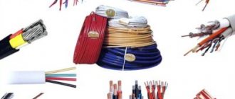
Specialized stores offer a wide range of wires for electrical wiring, so for phase and zero it is better to take wires of different colors, for example, red and blue.
So, a two-wire cable runs from the distribution board to the distribution box. It is very convenient if it is two-colored, for example, the phase wire is red and the neutral wire is blue.
In addition, a cable from the lamp and a cable from the switch are suitable for the junction box. The phase wire from the distribution board (red) is connected to the red wire going to the switch.
The second (blue) wire from the switch is connected to the red wire, which is connected to the load (lamp, chandelier). As a result, we made the phase that goes to the lamp commutated.
The neutral wire (blue) from the electrical panel is connected to the neutral wire, which goes to the load (light bulb).
The result is that the neutral wire from the junction box goes directly to the light bulb, and the phase is connected to the light bulb through a switch.
The scheme works as follows. When you press the switch key, the circuit is closed, and the phase from the electrical panel is supplied to the lamp, its light bulb begins to shine. By pressing the key again, the electrical circuit is broken and the light bulb turns off.
After all connections, the twisting points are thoroughly insulated and neatly laid. It is best to connect the wires in the junction box by twisting and soldering.
Connection diagram for socket and switch in one junction box
Very often, a distribution box is installed in each room of the apartment, where all the switches, lamps and sockets of this room are connected.
In this case, due to the large number of wires going to the junction box, it is quite difficult to figure out what needs to be connected where.
How to connect a socket and switch to a distribution box?
Let's consider the option when a socket and a lamp are simultaneously connected to one distribution box.
So, two wires come from the distribution board to the box - red (phase) and zero (blue).
The procedure for connecting the switch and lamp is exactly the same as discussed above.
The socket is connected parallel to the supply wires: the socket phase is connected to the supply phase (both wires are red), and the zero from the socket is connected to the neutral supply wire (both wires are blue).
The connected wires must be well crimped and soldered, after which they are securely insulated and neatly placed in the box.
Any modern room needs to be equipped with basic electrical contactors for connecting electrical equipment and lighting. Let's look at how to connect a socket, a switch with wiring and a light bulb, as well as the basic circuit, the most common options and their features.
Connection diagram for a lamp when combining a socket and a switch in one unit
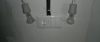
A socket and a switch combined in one housing are far from uncommon. Today factories produce them in large quantities. Their main advantages are saving wires and space, lower labor and time costs and high operational safety. To connect the device to a light bulb, you must perform the following steps:
- Prepare a place on the wall surface for a socket box. Modern houses made of reinforced concrete elements already have mounting holes with wiring. If they are not there, you need to use a hammer drill. In wooden houses, overhead structures with external wiring are often used.
- A two-core wire is laid from the main electrical panel to the distribution box. Phase and zero will follow it.
- You also need to connect the para-core conductor from the light bulb and three wires from the block with the switch and socket to the distribution housing.
- The current source in the panel is connected with wires: the phase is sent to the socket and switch.
- The neutral conductors of the light bulb and socket must be connected to a similar wire of the general electrical network.
- The remaining two wires (coming from the chandelier socket and the switch) are combined and isolated.
- If there is a ground conductor in the housing of the socket switch, it is necessary to connect it to the ground conductor.
Read also: Soldering HDPE pipes with a soldering iron
This connection diagram will allow you to use devices combined into one module independently of each other. However, there is another technique - when current is supplied to the outlet in the switched position and vice versa. With this option, the algorithm of actions is as follows:
- The installation site is being prepared (according to the diagram above).
- Three two-wire conductors are supplied to the distribution box - in pairs (phase + zero) from the socket, switch and panel.
- The phase conductor of the common network must be connected to a similar wire of the switch.
- The zero branch is twisted with the wire from the outlet
- The two remaining free conductors in the device are connected to each other.
Important! The given connection diagram for an socket switched by means of a switch is suitable for rare use. For example, it can be used to turn on and off a light bulb in a basement powered by an extension cord with a plug.
Varieties
Differences between modules can be made by:
- design features;
- design;
- component material.
If we talk about the second element of the highlighted list, then the design is a matter of a personal nature and everyone chooses what he likes best based on the color or design that was developed by this or that company. The interior of different modules also differs. This, for example, concerns the base where the contacts are secured. Previously, it was popular to make it from ceramics. But finding really good products with ceramic inserts is quite difficult. In most cases, over time it begins to crumble and weakens the contacts.
The best option, which is used everywhere, is ABS plastic. Sockets and switches use a type of base that is refractory. Even with a short circuit, no fire occurs, but only melting of the insert
It is also worth paying attention to the metal from which the contact group is assembled. Copper is considered the best, which can be identified by its characteristic reflection, but you should be careful because
because unscrupulous manufacturers coat ordinary metal with paint similar in color to copper; to determine whether this is so, it is enough to scratch the contact a little.
The issue of differences in design features is more complex. According to the method of association, they are distinguished:
- single-hull models;
- with installation in a common frame.
Single-case models have one factory case, which houses a common filling for two elements. The disadvantage of this option is that the switch can be powered through the outlet, which loads it additionally in addition to the connected consumer. The second option is used more often. It involves the purchase of absolutely equivalent modules, each of which has its own filling. Before installation, the single frame from the socket and switch is dismantled, and they are installed in a common frame, which can combine up to 12 or more elements, if required. The correct connection method in this case would not be parallel, but to supply each switch or each socket with its own conductor. Externally, this version looks more elegant than the previous one.
Depending on the installation method, the following types are available for sale:
- internal;
- external.
Outdoor sockets, which have a common housing with a switch, can be installed in any required location. They are fixed using the overlay method. There is no need to prepare holes for this. This option is more suitable for utility rooms or residential areas as a temporary solution. Internal modules require drilling a hole and installing a special box in which the core of the socket or switch is fixed.
The designs also differ in the way they are laid out. If we talk about options that are mounted in one frame, then there are only two solutions: vertical and horizontal arrangement of the frame. When purchasing, you should be careful, because the fastenings for each of these frames are different. In the case of single-case solutions, the variety is greater, since the switch can be the same size as the socket, or smaller than the socket. In the second option, the switch can be located in any position and have any shape: round, rectangular or square. Some modules are assembled in such a way that the presence of a switch is not immediately obvious.
The difference may lie in the number of keys on the switch, which is combined with the socket. In some cases, there are three or four of them on one element. Some switches may be backlit, making them easier to use in the dark. According to the method of operation, the switch can be installed as a break or pass-through. In some cases, a switch mechanism is used in which the key does not occupy the extreme position, but returns to its original position. Options with a wireless switch are also available, which require the installation of an additional receiver on the lighting.
Note! Blocks with outdoor installation can be protected from moisture, which allows them to be installed in basements, cellars, garages or other rooms where there may be high humidity
How to connect a single-key switch from an outlet
Often, in solving practical problems when connecting additional lamps or just light bulbs, the need arises to connect a switch from the outlet. You can do this in two ways:
- By connecting the phase from the socket and the neutral to the ground from the distribution box, when the lamp is close to the latter.
- Connecting phase, neutral and ground from the socket when the light bulb is far from the source and pulling wires across the entire apartment is impractical.
Interesting! Ultimately, it is up to the owner to decide which option to choose. However, it should be taken into account that if the outlet is constantly loaded with powerful devices, then its contacts can quickly weaken. Over time, this will lead to deterioration of the lighting device's power supply. The mechanism of sequential actions for connection for both versions is no different (except for the connected power) from when the socket outlet is already connected and in operation, and is given below.
Preparatory work
Before proceeding directly to the connection process, you should complete a number of preparatory work and decide on the location of the future switch. Preparatory work includes work related to the selection of the wire, the switch itself and the circuit that it will power.
Wire selection
Before connecting a switch from an outlet, we should correctly select the wire with which the connection will be made. After all, choosing the right wire will significantly reduce the likelihood of a fire or other breakdowns.
- To select a wire, we need to know the rated power of the electrical appliances being switched, from which it is then not difficult to derive the rated current. This is done according to the formula, where I is the rated current, P is the rated power, and U is the rated voltage, which for a single-phase network is 220V.
- Having calculated the rated current, we can use table 1.3.4 PUE for copper conductors or table. 1.3.5 for aluminum wires, to select their nominal cross-section (see Calculating the wire cross-section by power).
Note! In most cases, when you connect a switch from an outlet, it switches one or two light bulbs. Because of this, the rated current is small and according to the table. 1.3.4 and 1.3.5, you can use a small cross-section wire. But according to the table. 7.1.1 PUE, the cross-section of this wire in any case cannot be less than 1 mm 2 for copper wire or 2.5 mm 2 for aluminum.
- Another aspect to consider when choosing a wire is the way it is laid. Indeed, if it is laid indoors in an open way on insulators, according to Table 2.1.1 of the Electrical Installation Regulations, its minimum cross-section should be 1.5 and 4 mm 2, respectively, for copper and aluminum wire.
- If the wire will be used for external laying in an open manner on rollers or insulators, then its cross-section in general should be no less than 2.5 and 4 mm 2, respectively, for copper and aluminum wire.
Switch selection
Before you power the switch from the outlet, it is important to choose the right switch itself. This aspect is often neglected, which is why switches often fail. This aspect is especially important if the switch will switch large loads.
- First of all, we select the switch according to the rated current. When choosing a wire, we have already calculated the rated current of our network, therefore, using the same numbers, we select the rated current of the switch. Currently there are 6, 10 and 16A models on the market. More powerful switches can be found, but they are rare.
- The next important selection factor is the method of mounting the switch. For hidden wiring, a recessed version of the switch is used, and for open wiring, respectively, with an outer box. Here the choice depends entirely on the method of laying your electrical wiring. The only exceptions are bathrooms and showers, in which paragraph 12.22 of VSN 59 - 88 recommends using only hidden wiring. But given that it is prohibited to place switches in these rooms, the method of installing the switch can be any at your discretion.
- Our instructions also advise taking into account the installation location of the switch. For outdoor installation, switches with IP no lower than 44 should be used. Of course, it is better to use switches with a higher degree of dust and moisture protection, but the price of such models increases in proportion to the level of protection.
If you need to install a switch from an existing outlet
If the outlet is already installed and connected, you can also connect a light switch to it. There are also two options here, the choice between which depends on the location of the chandelier. The difference between them lies in the distance of the lamp from the socket - if close, then the neutral core is in contact with it, if far away, then from the shield. Let's consider both methods.
Phase and neutral supply from the socket
The easiest option is when both phase and zero are connected to the switch from the outlet. It is applicable if the light bulb/lamp is located very close. To connect them, you need to do the following:
- First of all, you need to install the chandelier itself, and then, according to all the rules, connect the switch to it through wiring.
- The connection procedure must begin with a circuit break - de-energization. This can be done by turning off either the group switch (for the room, if there is one) or the common switch (for the entire apartment/house).
- Next, open the socket cover and check the current at its contacts using a special measuring device (screwdriver with a light bulb).
- A conductor leading to the switch input is connected to the contact with the phase. The output is connected to the core of the lamp itself.
- A conductor suitable for the terminal from the lighting device is attached to the zero contact.
- If there is a grounding contact, then it must also be connected to the corresponding conductor of the chandelier.
- After all the wires have been correctly twisted, the contacts are closed, the wires are laid in their intended place, and the entire assembled system is tested after applying voltage.
Important! When all electrical appliances in a residential area are connected in accordance with PUE standards, in particular, paragraph 1.1.29, then the zero will correspond to a blue conductor, and the ground will have a yellow-green hue. Therefore, determining the phase will not be difficult. Otherwise, a temporary voltage supply will be required for identification using the device.
Connecting only phase
Now let's consider the option of how to connect a switch to an outlet if the chandelier is located in close proximity to the switchboard. To do this you need to do the following:
- As in the case described above, first of all you should break the circuit by de-energizing the work area.
- Next, remove the cover from the socket and check for voltage (for safety).
- If the phase contact cannot be established visually, it is checked using a measuring device and temporarily applying voltage.
- A conductor is attached to the phase contact of the socket and brought to the switch input.
- The core from it must be connected to the input of the lamp.
- The neutral conductor is laid either directly from the shield (which is extremely rare) or from the distribution box closest to it.
- In the same way, it is necessary to connect the grounding conductor for the light bulb.
- After twisting the wiring, reliable insulation of the contact points and applying voltage, the serviceability of the assembled system is checked.
Important! Connecting a switch from an outlet is a completely solvable task. However, the reverse action is not feasible in practice. The first has only a phase conductor, and for the second to work, a zero one is also required. It will need to be carried out from the panel or junction box. However, even in this case the result will not be satisfactory.
To power the lamp, a large current is not required, and therefore the wire is taken with a thin cross-section. The socket output requires a thicker conductor - a regular phase conductor from the switching mechanism will quickly overheat and burn out. The latter circumstance can even lead to a dangerous fire situation!
Recommended wires for boxless wiring
Conductors with 4-6 mm2 conductors were laid between the distribution boxes, and taps were made from it for individual sockets and lighting fixtures with thinner wires. The common wire was designed for the load of all consumers in the group. In our version, a cross-section of 4-6mm2 will not be very convenient for connecting to contacts and packaging in socket boxes.
Such wires are rigid, difficult to clamp with bolted connections of the contacts, sometimes the terminals even break. It is very convenient to use 2.5 mm2 copper wire, it is elastic and fits perfectly into the terminal grooves. The current loads that the cores can withstand can be seen in the table. Based on this, make calculations on the number of sockets in the group and the power of connected household appliances.
| cross-sections of copper conductor for various current loads | ||||||||||||||
| Current in A | 1 | 2 | 3 | 4 | 5 | 6 | 10 | 16 | 20 | 25 | 32 | 40 | 50 | 63 |
| S - in mm2 | 0,17 | 0,33 | 0,52 | 0,67 | 0,84 | 1 | 1,7 | 2,7 | 3,3 | 4,2 | 5,3 | 6,7 | 8,4 | 10,5 |
| Ø in mm | 0,45 | 0,65 | 0,81 | 0,92 | 1,02 | 1,13 | 1,45 | 1,87 | 2,05 | 2,32 | 2,60 | 2,92 | 3,27 | 3,66 |
Based on the calculated values, a 2.5 mm2 wire can withstand a load of up to 16A. Data have been collected on the approximate powers and currents consumed by household appliances for various purposes. Using this information, you can guess how many and what devices to include in the outlet group.
| Type of household appliances | power in W | current in Amperes |
| Old style incandescent lamps | 60 – 250 | 0,3 – 1 |
| Small-sized heating appliances: teapots, coffee pots and boilers | 1000 – 2000 | 5,5 – 10 |
| Stationary and portable electric stoves | 1000 – 6000 | 6 – 55 |
| Microwaves of various brands | 1500 – 2200 | 8 – 10,5 |
| Kitchen electric meat grinders for non-industrial purposes, for home use. | 1500 – 2200 | 8 – 10,5 |
| Toasters for baking bread | 500 – 1500 | 2,5 – 8 |
| Equipment for preparing grilled dishes | 1200 – 2000 | 7,5 – 8 |
| Blenders and mixers | 500 – 1500 | 2,5 – 9 |
| Food processors | 500 – 1500 | 2,5 – 9 |
| Electric oven | 1000 – 2000 | 5,5 – 8 |
| dishwashing machines | 1000 – 2000 | 5,5 – 8 |
| Household washing machines | 1200 – 2000 | 5.5 – 8 |
| Electric shoe or clothes dryers | 2000 – 3000 | 8 – 12 |
| Irons for non-industrial use | 1200 – 2000 | 5.5 – 8 |
| Floor and portable vacuum cleaners | 800 – 2000 | 3.5 – 8 |
| Spiral heaters | 500 – 3000 | 1.8 – 12 |
| Hand-held hair dryers | 500 – 1500 | 1.5 – 7 |
| Split systems and air conditioners | 1000 – 3000 | 6 – 12 |
| computers | 300 – 800 | 0.8 – 3,2 |
| Hand-held power tools (grinder, drill, hammer drills, jigsaw, etc.) | 500 – 2500 | 1.8 – 12 |
For lighting devices, it is recommended to lay a three-wire cable from 0.7 to 1 mm2. Practice shows that this is quite enough, especially when LED lamps and energy-saving lamps are used.
Is it possible to connect an outlet to the switch?
Full joint operation of the socket and switch, if the first is powered by the latter, is almost impossible. However, there are some variable methods to combine them. Let's look at them in detail.
Socket instead of switch
You can install an socket instead of an existing switch, for example, when you need to carry out a number of temporary repairs or decoration work using electrical equipment or connect a light bulb on a portable device. In this case, you need to perform the following series of actions:
- Turn off the machine - de-energize the network. Before work, you need to make sure that there is no voltage on the contacts using a test probe.
- Disassemble the switch and remove the wiring that goes to it.
- Dismantle the base of the switch, and in its place install a socket and connect its contacts to the freed wires.
- Next, you need to remove the cover of the junction box and disconnect the wires from the former switch from the wires going to the light bulb.
- Connect one of the conductors from the new outlet to the phase, the other to zero and cover them with a layer of insulation; the wires from the lamp are temporarily brought together and insulated.
- Close the distribution module cover and turn on the switch.
- Check the socket, for example, by connecting a plug with an adapter and a light bulb. If it lights up, the circuit is assembled correctly.
Read also: What can you cut with a miter saw?
Connection from double switch
A two-key switch can also be connected to a power outlet to power electrical appliances, but in this case only one key will work. The algorithm of actions is as follows:
- It is necessary to de-energize the electrical network, be sure to check the contacts with a measuring probe before work.
- Install the socket and two wires connected to it.
- Next, you need to disassemble the switch and free the input and one of the two output wires.
- Connect one wire of the socket to the input contact (phase).
- Connect the second conductor of the socket (zero) to one of the output wires from the switch (the one that was previously disconnected) and insulate it.
- Having opened the cover of the junction box, it is necessary to disconnect the neutral conductor for one of the light bulbs and connect it with the same conductor that was disconnected at the output of the switch and twisted with the neutral conductor of the socket.
- All contact connections are insulated, and the covers on the switch, socket and distribution module are closed.
- The switch is turned on and the operation of the circuit is checked.
Main conclusions
You can connect a socket to a switch for various purposes and in different ways:
- Independently in one housing for convenient use, when the power supply for electrical appliances and the switching mechanism for the chandelier are in one place.
- In a switchable module for connecting a carrier with a light bulb, heater or tool.
- The switch is powered from the contacts of the socket when the lamp is located nearby, and it is unprofitable to wire it separately.
- The socket is connected from a switch temporarily instead of a one-button mechanism, or permanently from a two-button mechanism with the obligatory transfer of contacts in the distribution box.
The main thing is not only to connect all the contacts correctly, but to ensure their safe operation in the future. Therefore, when choosing a circuit and conductors for connecting a socket, switch and light bulbs, you need to correctly select the wire according to its cross-sectional area. Also, we must not forget about the personal safety of the master and always check the presence of voltage in the network before work using a measuring tool.
Electrical wiring of any room, be it a huge country house or a small outbuilding (basement, garage, country house), includes three main elements - a switch, a socket and a light bulb. While they remain relevant always and everywhere. During repairs, construction or redevelopment, you will definitely encounter them. Therefore, basic knowledge of electrical engineering will not be superfluous - what is the connection diagram for a switch and socket, how does it work and what materials and tools will be required for its installation?
Below are detailed step-by-step instructions, with the guidance of which even a not very experienced electrician will be able to install sockets and switches with his own hands.
What is needed to switch the circuit?
Electrical wiring can be open or hidden. In this article we will consider the connection of sockets and switches made according to the second option, when all electrical switching is hidden under a layer of plaster. Hidden design is the most common type of electrical wiring; open wiring is usually used as a temporary option.
Preparing the walls
Before connecting a socket and switch in the room, you need to prepare holes in the wall for their installation and grooves in which the wires will be laid. There should be three holes in total - for the junction box and for the connected switching devices.
It’s better to draw an approximate drawing on a piece of paper in advance, where exactly you plan to connect the switch and socket, and what route the wires will take to these places.
The hole for the distribution box is made, as a rule, under the ceiling, 10-15 cm lower. Holes for switching devices are made at the site of their planned installation. It is better to install the socket at a distance of 30 cm from the clean floor, where household appliances will be connected to it. It is advisable to install the switch at the entrance to the room at the level of an adult’s lowered hand - about 90 cm from the clean floor. These works are performed with an electric drill with a special bit for brick or concrete, a hammer drill with a Pobedit drill, an impact drill or an angle grinder.
When installing gates, consider several important rules:
- They can only be horizontal or vertical; no tilting is allowed.
- The entire path of the groove from the distribution box to the installation sites of the socket and switch must pass with a minimum number of turns.
- Vertical grooves cannot be brought closer to window and door openings less than 10 cm, and to gas pipes - less than 40 cm.
To install the grooves, you can use a hammer and chisel, a hammer drill, a grinder or a special tool - a wall cutter.
When all the holes and grooves are ready, thoroughly clean them of dust using a vacuum cleaner.
Installation elements and tools
To perform the electrical part of the work you will need the following materials and tools:
- distribution (socket) box, in which all wires are connected;
- two plastic or polypropylene mounting boxes (socket boxes), they are needed in order to securely fasten the switching devices in the wall openings;
- indoor socket;
- indoor switch with one key;
- lighting fixture;
- set of screwdrivers (flat and Phillips);
- knife or stripper for removing insulation from conductors;
- pliers with insulated handles;
- clamps or insulating tape;
- indicator screwdriver.
To switch the entire electrical circuit, you will also need a two-core wire. Nowadays, electrical goods stores offer a huge assortment of wires and cables, so immediately buy one so that each core has its own colored insulation, for example, red and blue. This will make it easier to switch the circuit; you won’t have to look for phase and zero with instruments, you’ll just need to connect wires of the same color.
Read also: Do-it-yourself sand for sandblasting
In order to fix the wires laid in the grooves, you will also need alabaster and a spatula.
When is it better to use fused blocks?
Basically, combined electric points are used in conditions where:
- the socket is rarely used;
- there is a lack of space on the wall;
- There are no requirements for the design of the room.
In a house or apartment, the first two criteria correspond to the entrance hall and corridor. Here, power is used infrequently - to recharge the phone before going out, turning on the vacuum cleaner, etc. The shortage of space is due to the presence of cabinets, hangers, cabinets, mirrors, etc.
In a garage or workshop, aesthetics fade into the background, so they strive to make installation as simple and cheap as possible. This means that choosing a switch with a socket in the form of a single unit will be justified.
In a living room, on the contrary, there is no place for such a device. You cannot hang it below 90 cm - it will be inconvenient to use the switch. In such conditions, a wire sticking out of the socket will create discomfort and spoil the appearance of the interior. It is customary to place constantly used electrical points no higher than 30 cm from the floor.
Fused blocks are used if the outlet is rarely used.
You need to be guided only by common sense; no regulatory documents limit the scope of application of combined switches.
Therefore, if desired, you can install a combined unit in any room, incl. nursery or living room.
Connection diagram
The electrical circuit represents a parallel connection to the power source of a lighting fixture with a light bulb, a switch and a socket.
Preparatory work
After turning off the machine, you need to once again make sure that there is no voltage, now using an indicator screwdriver. First, check its working condition in an area that is known to be energized, for example, at the entrance to the machine. The indicator lights up after touching the phase, which means it is in good condition. Now touch the indicator screwdriver to the cores of the power wire, which is brought into the apartment from the machine; there should be no glow. This means that the tension has been relieved and work can begin.
Lay the wires in the grooves made, leading them to the wall holes. At the same time, leave the ends of 10-15 cm for cutting the cores, do not regret it, it is better to make a slightly larger reserve than to suffer later when connecting and connecting. Install a distribution box and socket boxes in the holes; use plaster or alabaster to securely fix them.
Electric installation work
Place a two-wire cable from the mains supply (phase and neutral) into the junction box. Three wires must be laid from the box: one to the switch, the second to the lamp, the third to the outlet.
For a wire whose cores have different insulation colors, red indicates phase, blue indicates zero.
The switch has an input and output contact; a phase conductor is connected to the input. Connect the second core to the output contact of the switch.
A two-wire wire must also be laid to the lamp. The lamp socket has two contacts. The central spring contact (phase) is used to directly supply voltage to the light bulb. The side contact in the socket is zero, the lamp will come into contact with it after screwing in with its base.
Another two-wire wire is laid from the junction box to the outlet. This switching device has a contact part consisting of two terminals to which phase and zero are connected.
The connection diagram for the switch, lamp and socket in the distribution box is as follows:
- Connect the neutral conductor from the supply wire with the neutral conductors going to the lamp and socket.
- Connect the phase conductor from the supply wire with the phase conductors going to the switch and socket.
- Connect the remaining core from the output contact of the switch to the phase core of the lamp.
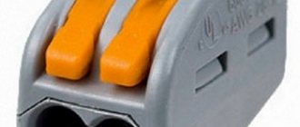
All connections must be made as firmly as possible to ensure reliable contact. This can be done the old fashioned way - by twisting, which it is also advisable to solder on top. There are also more modern devices: special blocks (in which the wire is clamped under a screw) or PPE (connecting insulating clamps).
For more information about connecting wires in a junction box, watch this video:
Checking the circuit and completing the work
Move all the twists in different directions so that they do not touch each other and check the operation of the assembled circuit. Turn on the input circuit breaker for the apartment, thereby supplying voltage from the power source to the newly mounted distribution box. The switch is in the “off” position, the lamp does not light, which means everything is correct, the phase is open. Now press the switch key to the “on” position, the electrical circuit is closed and voltage is supplied through it from the power source to the lamp, the light bulb lights up. There will be constant voltage at the outlet; you can check its operation by connecting any electrical appliance. Plug the hair dryer, radio or electric kettle into the outlet and check its operation.
Now turn off the input circuit breaker again and securely insulate the twisted areas with electrical tape; you can also put PVC pipes on top. Carefully place all the connected wires in the box so that it can then be closed with a lid.
All that remains is to securely place the switch and socket in the socket boxes, secure them, and put protective covers on top. The distribution box is also covered with a lid; during any repair work, never hide it under wallpaper or plaster. Remember, the distribution box should always be accessible, no matter how much it spoils the overall appearance of your room.
Also keep in mind that if the lighting fixture and socket are structurally grounded, then their electrical circuit will require a three-core wire. The same wire of three cores should also come to the junction box from the power source. Typically, the grounding conductor is indicated in green or yellow; in the same way, in the box you will need to connect three protective grounding conductors into one twist - from the power source, socket and lamp.
Device selection
Since the choice is quite large, you can find a model that matches the interior of the room . The devices also differ functionally:
- Regular switches.
- Devices with an indicator that can turn on in the dark to indicate its location or indicate which key is on.
- Pass-through switches. They are installed in different places in long corridors or passages, on stairs, on different floors, etc. Through them you can control one or a group of lamps from different places.
There should be no scratches, burrs, abrasions or other damage on the body of the product. The keys should be easy to switch with characteristic clicks, and the terminals should firmly fix the connected wires. Self-clamping terminals work reliably and are more convenient to use. Just insert the wire into the hole and it will be fixed
It is important to remove it correctly if necessary. For this purpose, the device has special latches that can be pressed out. If you pull the wire out of the hole, the connector may fail.
If you pull the wire out of the hole, the connector may become damaged.
Other scheme options
In a similar way, you can connect a socket, a two-key switch and two groups of lighting fixtures from one power source. In this case, the distribution box will receive two wires from two output contacts of the switch and two phase conductors from the lamps. The same as in the example described above, only there will be one more twist in the box.
If you need to install a three-key switch and three groups of lamps, then three wires from the three output contacts of the switch and three phase conductors from the lighting devices will arrive in the distribution box. There will be 5 twists in total in the box:
- Zero supply network with zero wires of the socket and lamp.
- Power supply phase with phase conductors of socket and switch.
- And three twists of phase wires extending from each switch key and group of lamps.
In the case of protective grounding, another twist will be added. Sometimes it can be quite problematic to arrange twisted wires in a junction box. Now on the electrical goods market you can select options specifically designed to accommodate a large number of wires and cables.
This is how you can easily connect a socket and a switch from one junction box. The main thing is to try to understand this very simple scheme. And then all further electrical circuits will be clear to you. As a result, you will get quite a decent cost savings on calling a professional electrician.
