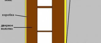
The canvases must have a continuous filling. It is true that it is up to the manufacturer to decide whether there will be a box or not.
By the way: according to this GOST, upper half-hinges must be installed on manufactured ones manufactured without boxes. The lower half-loop must be packaged and included in the product package.
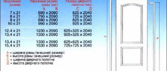
- The standard regulates the manufacture of structures of all types, according to clearly defined standard sizes. Marking according to GOST must reflect the height and width of the opening for which this product is intended. For example: DK 24-19 means: swing door, height 24dm (2.4m), width 19dm (1.9m), taking into account the thickness of the frame.
- Double-floor structures of the “O” and “G” types may have canvases that are unequal in width. The letters “P” (right) or “L” (left) are also added to the single-field marking. The additional letter “P” means that the product has a threshold - for example: DG 24-15PP.
- As for not the markings, but the graphic images on the drawings of the buildings being designed, they are carried out in accordance with the standard 21*201-2011. Paragraph 4.7 contains a table with sample graphic images of doors that designers should adhere to. We present this table below.
The manufacture of doors of all types must be carried out in accordance with the working drawings presented in this standard, and only in accordance with the permitted dimensions. Next, you will be offered a short excursion into the technology - it may be useful for those who want to make a wooden door with their own hands.
Assembly
Structurally, the canvases are divided into frame structures, consisting of strapping bars and panels, and panel structures. Making a frame door is more difficult, the material consumption is higher and it must be of high quality. Therefore, the price of this design is higher.
By and large, the panel door is based on the same frame, only with internal filling and lining with cheaper material: plywood or fiberboard 3-5 mm thick. Such doors are cheaper, but due to their hollow structure and filler they have higher sound insulation properties.
The set of technological operations in the manufacture of a panel structure is as follows:
- assembly of the frame and its filling
- cutting of facing parts
- gluing boards and processing their ends around the perimeter
- Installation of lining or layouts under glass
- Making a box for canvas
- Decorative door trim
To make a glazed door, two frames are made from bars with the same cross-section. The frame parts are connected at the corners with a tenon or with special clips. The filling of the frames can be very different: slats, stuffed at some distance or completely, MDF, plywood. If the filling is continuous, the assembly order will be as follows.
- A lining is applied to the finished frame on one side, spread around the perimeter with glue, and then secured with small nails 2-2.5 cm long. Then the frame is turned over and its internal space is filled with bars or slats. Their cross-section must correspond to the thickness of the door frame.
- You need to try to ensure that the filling elements are pressed tightly and their joints do not coincide. Next comes the turn of the second shield, which is mounted in the same way as the first. In the case when the filling of the frame is not continuous, but sparse, you need to try to ensure that the size of the cells does not exceed 4 cm.
- Furniture factories, of course, have their own technologies, and to fill the frames they use not lumber, but special honeycomb inserts made of pressed cardboard. After the frames are filled, the panels are glued onto them using a hydraulic press.
If pressing is done mechanically, then gluing takes quite a long time - up to half a day. When using the hot method, a quarter of an hour is enough for this.
About a day after pressing, the perimeter of the doors is processed. This includes filing of panels, cutting of grooves, and grinding. Finally, the lining parts and glass layout, if provided, are installed on them.
Metal doors: standard
The standard size of such a door is 203 x 90 cm. At least, many domestic manufacturers are guided by it. It should be taken into account that doorways in old and new buildings differ in size. Moreover, in the old ones the doorway is framed by a wooden frame, which does not need to be taken into account when taking dimensions. She's cleaning up. But in modern ones there is a metal “edging”. Therefore, if you want to expand the doorway, this will be difficult to do.
According to the nomenclature of goods subject to mandatory confirmation of conformity, entrance and interior doors (wooden and metal) are not subject to mandatory certification.
It should be added that the standards also stipulate standard section sizes for each type of door, installation methods and type of fastening material for various protective and design elements, and much more.
When choosing a particular door, you need to take into account the fact that large items will have to be brought in or taken out through the doorway. Experts recommend a minimum width of 90 cm. If the doorway is narrower, then it is just an emergency exit, and not a full-fledged door.
GOST requirements for fire doors
The requirements for limiting the spread of fire (namely, this is the function that fire doors perform) are established in Federal Law No. 123-FZ of July 22, 2008 “Technical Regulations on Fire Safety Requirements” (hereinafter referred to as Federal Law No. 123). According to this document, parts of buildings, structures, fire compartments, as well as premises must be separated from each other by enclosing structures or fire barriers. A more complete idea of what a fire door is is given by GOST R 57327-2016.
A fire door in this document is described as a structure of moving and fixed elements with locking mechanisms, self-closing devices and fastening elements. The purpose of this design is to prevent the spread of fire and combustion products.
- “GOST R 53303–2009. Building structures. Fire doors and gates. Test method for smoke and gas permeability", with change No. 1, effective from September 1, 2014;
- "GOST R 53307–2009. Building structures. Fire doors and gates. Test method for fire resistance." These documents explain how to properly test and evaluate the quality of a finished fire door.
Despite the fact that, as a general rule, standardization in Russia is voluntary, the application of the above national standards may be mandatory for the manufacturer.
GOST requirements for fire doors
We are talking about cases when he publicly declares the compliance of his product with national requirements and records the corresponding designation in the labeling.
In other words, if a manufacturer declares compliance with GOSTs, he is obliged to certify his products; in our case, he is obliged to certify the door as fireproof.
As for the buyer (the head of the organization), it is he who is responsible for compliance with fire safety requirements, including, for example, for the good condition of fire door mechanisms (clause 37(1) of the Government of the Russian Federation of April 25, 2012 No. 390 " About the fire safety regime"). That is why purchasing doors that meet state standards is no longer a luxury, but a vital necessity. How to understand the types of door blocks and their characteristics? We will try to answer this question in the next section.
Education
Reading drawings for designers just starting out is a fairly simple task. You just need to know by heart all the symbols and other information contained in the plan, which is understandable only to a narrow circle of people who have been trained in the chosen construction specialty. In principle, anyone can learn to read construction documents easily and fluently. To do this, you just need to understand the system of symbols, learn to distinguish materials from each other, which will allow you not to confuse, say, sand with corrugated steel. It just takes effort and a little practice. And even the most absent-minded person can easily read the drawings.
Rules for drawing up drawings according to ESKD
When preparing drawings, pay attention to 5 main points:
- sheet format;
- scale;
- lines;
- size;
- font.
Sheet format and design
The design of the sheet is regulated by GOST 2.301-68. Drawings are drawn up on A4 sheets - 297*210 cm. Parameters of other formats are specified in GOST.
Requirements for sheet format according to GOST
First, a frame is drawn on the sheet that defines the boundaries. It is designed with solid thick lines. On the left, a distance of 20 mm is maintained for hemming. To the right from the outer edge to the frame - a distance of 5 mm.
Information is indicated at the bottom right. Solid thick lines are used for graphs.
Example of frame and information design
Main inscription
The title block is required for drawings of all scales. It is regulated by GOST 2.104-2006. The main inscription is located at the bottom right. Solid thick lines are used for graphs.
The following information is indicated in the columns:
- the name of the product in the nominative singular case, for example “Wheel”, if the name of the product consists of several words, then the noun “Geared Wheel” is put in first place;
- designation of the drawing according to GOST 2.201-80. For example, UZ.KCH0115.000. UZ - educational institution, KCh0115 - drawing course, task one, option fifteen, 000 - serial number of the part
- designation of the part material;
- letter assigned to the document (letter U);
- product weight in kg;
- scale
- serial number of the sheet;
- the total number of worksheets completed during the semester;
- study group number;
- nature of the work;
- last name of the student and teacher;
- signatures;
- date of signing of the drawing.
Example of title block design
Scale
Scale is the ratio of the image sizes in the drawing to the actual dimensions of the product. To draw products with non-standard sizes, the rule is used: large ones are reduced, small ones are increased.
The following types of scale are distinguished:
- Life size is rare - 1:1. The most convenient, as the size of the product is immediately clear.
- Reduction scale - 1:2; 1:2.5, etc. Used for large products, for example, aircraft parts.
- Magnification scale - 2:1; 2.5:1, etc. Used to depict a small product, for example, a part for a watch mechanism.
- Particular scales of reduction are calculated using special formulas. Used by architects to depict very large objects, such as bridges.
- Specific magnification scales are calculated using the formula. Used for microscopic parts.
GOST 2.303-68 will help you calculate the scale. Indicate the scale in a special field in the frame.
Often the drawing shows details of different scales. This happens when it is necessary to demonstrate the design features of a product. For this purpose, cuts, sections, and extension elements are used.
They are smaller in size than the main part, which means the scale is different. It is indicated next to the element by placing the letter M in front of the numbers - M 1:1; M 1:2; M 2:1.
An example of indicating the scale in a drawing
Lines
For the drawing, lines of different thicknesses are used. There are 6 types in total. Regulated by GOST 2.303-68. The line type is selected depending on the work format.
- Solid thick main is used to indicate outlines, frames and graphs of the title block.
- Dashed lines show invisible contours. The dashed lines should be the same size, and the space between them should be the same in length.
- A thin dotted line draws the axis of symmetry. It shows the axes of rotation, the center of circular arcs.
- Extension and dimension lines with a thickness of s/3-s/2 are drawn in solid thin lines.
- A dotted line + 2 thin dots indicate the fold lines.
- Solid wavy indicates a break when the image is too large to fit on one sheet.
Types and characteristics of lines for drawings
Dimensions
Dimensions are needed to determine the dimensions of the product. Angular dimensions describe the size of an angle in degrees, seconds, minutes. The unit of measurement is indicated.
Linear - length, width, height, diameter, thickness and radius of a part of the product. These figures are indicated in mm. The unit of measurement is not specified.
An example of specifying dimensions in a drawing
Font
The drawings use a special drawing font with regulated parameters for letters, numbers (size, angle) and the distance between words.
Example of a drawing font
How to depict (display) doorways, doors on a house plan in AutoCAD
Measuring and determining the dimensions (width) of doorways on the house plan AutoCAD
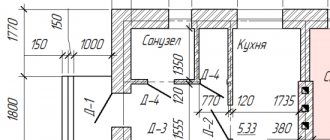
Call the “Dist” command in AutoCAD from the classic “Information” toolbar, “Distance” button, or in the “Home” tab of the “Utilities” toolbar, “Distance” button and measure the width of the doorways on the AutoCAD house plan. The size (width) of the doorway on the plan was 718 mm.
In the same way, we measure the width of the remaining doorways in the drawing of the plan of the first floor of the cottage. We obtain the values of the width (dimensions) of the door openings = 718, 1524 mm.
Below is a picture of the standard sizes of doorways “Dimensions of doorways in walls” . According to GOST data, the dimensions of doorways for the cottage plan are 710 mm (I chose the size of the doorway in the house 810 mm), 1510 mm.
How to make doorways on a house plan in AutoCAD (algorithm)
To create doorways in AutoCAD, I used the following algorithm (you can use any convenient method for creating doorways on the plan):
Select the Line tool from the Draw toolbar in the Home tab of the Tools Ribbon and draw the first wall of the doorway.
Select the “Copy” tool in the “Editing” toolbar in the “Home” tab of the tool ribbon and copy the wall of the doorway to a distance of 810 mm, i.e. by the width of the doorway. To track perpendicular angles and polar angles in AutoCAD, you will need polar snapping or ORTO mode.
Select two segments indicating the doorway on the house plan, and group them for ease of working with the doorway and placing it in positions according to the plan of the first floor of the cottage. You can group objects in AutoCAD from the context menu. Click the right mouse button and select the line “Group” – “Group” in the context menu.
Using the “Copy” and “Rotate” commands in AutoCAD, copy the doorways and place them according to the drawing of the house plan.
Designation (image) of doorways on the house plan in AutoCAD, line thickness
We built doorways on the house plan in AutoCAD, but the designation (image) of them on the house plan does not end there. The fact is that you also need to observe on the plan the thickness of the wall lines in the doorways!
In order not to redraw the walls of the house that run directly into the doorways, break them at a special point with the “Break at point” tool of the “Break” command in AutoCAD.
For the convenience of changing the thickness of wall lines from thick to solid thin, passing through doorways, use the “Copy Properties” tool in AutoCAD.
Move the walls passing through the doorways to the “Rooms” layer. We created all the necessary layers for drawing a “House Plan in AutoCAD” in the lesson on setting up AutoCAD for making architectural and construction drawings.
How to conventionally designate doors on a house (cottage) plan drawing
Conventional designation of doors on the plan - the door leaf is equal to the width of the doorway and opens 30 degrees.
How to draw (draw) a door on a house plan in AutoCAD (algorithm)
Select the part of the wall passing through the doorway, which we left so that in the future our shading will not flow out of the rooms.
Activate the segment handle by clicking on it (see picture). Right-click on an empty space in the drawing and select “Rotate” from the context menu. Specify a rotation angle of 30 degrees.
Call the “Arc” tool from the classic “Drawing” toolbar, the “Arc” button, or in the “Home” tab, the “Drawing” toolbar, the “Arc” button with the “Start, Center, End” construction method. Draw an arc as shown in the figure.
The designation of the door on the house plan was made in AutoCAD. Now copy the door using the “Copy” tool across all doorways of the first floor plan of the house, and to make it easier to work with the door designation, group the door objects. Select the door objects (segment, arc) and right-click. From the context menu, select the “Group” line – in the drop-down list, select the “Group” line.
AutoCAD commands and tools used to create doorways, doors on the house (cottage) plan:
Metal door blocks
Nowadays, wooden entrance doors are installed mostly in private buildings. In multi-storey buildings, preference is often given to iron doors - and they are manufactured in accordance with a different standard: 31173*2003. This document sets requirements for the manufacture of metal blocks with devices embedded in them that prevent unauthorized entry into the premises.
As for the standard for the doors themselves, it applies only to metal blocks installed in civil buildings for various purposes, as well as residential ones. As for doors for special purposes, which must be, for example, bulletproof, or be resistant to an explosion or fire, they are manufactured according to completely different regulatory documents.
Classification and labeling
Metal doors are classified according to indicators such as design, mechanical characteristics, operational requirements, type of finish. Structurally, they are distinguished by the box: it is possibly U-shaped; U-shaped with a threshold; closed.
- Another method of design difference is the option and number of openings of the canvases. They can be single-sex, as well as left and right. They can have two canvases: both uniform and of different widths - as well as one that does not open. And the doors can open either inside or outside the house.
- Based on the number of contours placed in the vestibule, only two manufacturing options are possible. The door, in most cases, has either one circuit or two - it is no longer very uncommon, despite the fact that GOST also allows this.
- The finishing of iron doors can be quite varied. Not counting paint and powder coatings, these are all kinds of cladding: leatherette and insulated leather; glued PVC films; tiles and wooden slats; veneer; glass; decorative iron elements. In addition, doors manufactured in accordance with GOST 31173*2003 can also be combined.
- Iron doors are marked according to the same principle as wood doors, only the dimensions are indicated not in decimeters, but in millimeters, and a strength class designation is added. For example, the marking DSV DKN 2100-1270 M3 stands for: internal metal door, double-leaf, with a closed frame, opening outward. Height 2100 mm, width 1270 mm - strength corresponds to class M3.
Complete door blocks made of metal must be delivered to the client assembled, as well as with installed locks. Upon additional agreement, the door may be equipped with a closer, a viewing eye or an opening limiter.
A complete set of keys must be sealed in an envelope and handed over to the client against signature. They are accompanied by a product passport, plus installation instructions from the manufacturer.
- https://www.kp.ru/guide/protivopozharnye-dveri.html
- https://blog-oremonte.ru/dveri/markirovki-dveri-i-gost-oboznacheniia.html
- https://mils-dveri.ru/articles/markirovka-dveryay.html
- https://masterim.guru/strojmaterialy/razmery-vxodnyx-dverej-po-gost/
- https://www.metal-tehdoor.ru/articles/markirovka-dverey-v-proektnoy-dokumentatsii.html
Doors
One of the most common elements of buildings and structures are doors. They can have a wide variety of designs, but the most common are:
- Single-sex
- Double-field
- Swing
- Recoil
Based on the material they are made of, they are classified into:
- Wooden
- Metal
- Glass
To install doors, frames are installed in doorways. If wood is used for this purpose, then such structures are made from bars and then attached to the wall. Wooden panels are usually made from a material such as laminated boards. Often, chipboard is used for this purpose, which is finished with facing materials.
Metal door frames and their frames are made from galvanized cold-formed steel profiles, which are subsequently painted to give the structure an aesthetic appearance and protection against corrosion. The door leaf of metal doors consists of one or two steel sheets, a frame and stiffeners.
The structural elements of glass door leaves are a frame made of aluminum or steel profile, and a leaf made of so-called “stalinite” (that is, tempered glass, characterized by increased strength).
According to current norms and standards, all entrance doors to buildings and apartments must open outward, that is, in the direction of movement to the street. This is necessary in order to facilitate the evacuation of people from buildings in the event of various emergencies (for example, fires).
Wooden plugs treated with antiseptics are used to secure door frames in openings. They are installed directly into reinforced concrete panels at the manufacturing stage of these structures. If the doors are external, then they are installed together with thresholds, and if internal, then without them.
To hang door panels on door frames, hinges are used. If the door is wide open, it is very easy and simple to remove it from its hinges. In order to avoid doors being open or slamming, special devices called “diplomat” are used. They serve to keep the door closed, and if they open, then return it smoothly, without blows. In addition, the doors are equipped with mortise locks, latches and handles. Entrance doors are often equipped with combination locks.
Hard materials
The designation of a hard alloy in construction documentation is usually represented by a standard rectangle, inside of which there are lines of diagonal hatching, made from top to bottom, from left to right. If you look closely at a section of a thick piece of iron, you can confidently say that the designation is similar to the internal contents of the materials.
Plastic and its derivatives are indicated in the drawing by a simple rectangle covered with a cross-shaped diagonal hatch, shaped like the porous component of the structure of any plastic compound.
The designation of wood in the drawing is a rectangle filled with uneven wavy lines, shaped like the age-old rings of a tree cut. Associative connections allow the builder to quickly find parts of the house made of wood in the drawing due to the similarity of the natural wood texture with the designation of the material.
Who creates the markings
When choosing fireproof structures, customers often have a question about the meaning of incomprehensible digital and letter designations, which usually appear next to the trade name “fireproof door”. In addition, the most attentive buyers are interested in why these designations are not the same in different projects. So where do they come from and who were they invented by?
It should be noted that such marking is completely arbitrary, and often each manufacturer writes and creates it himself. Using letters and numbers, a brief description of a specific door model is expressed.
The most resourceful manufacturers even insert the name of their own company into such a homemade article, for example: PULSE DPM-01/60. The brand name of the door can also be used, for example – Entrus D1 EIS60.
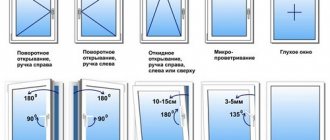
Pen
It is worth remembering that the right hinge opens the sash in a certain direction. If you purchase a handle designed for a right-hand door and try to install it on a different type of door, serious problems will arise. Firstly, the handle can only be installed upside down, which will not have the best effect on its performance characteristics. During operation, the handle will periodically begin to jam, and then stop opening.
When choosing a suitable pen, you should pay attention to designer products. They will become the main decoration of the model. It is important that the color of such a product matches the door system, as well as the interior of the room.
What other designations can be used
We have thus found out how interior doors installed directly in buildings can be marked. The second position for such models indicates the type of construction.
However, in various types of buildings, of course, external doors are almost always used. In the marking of such products, the second position may contain, for example, the following designations:
- “N” - entrance doors or tambour-type models.
- "C" - service doors.
- “L” - hatch doors or manhole models.
If there are such letters in the marking, the letters indicating the actual type of construction “G”, “O”, etc., can be transferred further - behind the numbers.
Unlike internal doors, entrance models are manufactured according to the standards provided for by GOST 24698-81. The same document also regulates their designations.
The numbers in the marking of internal doors, as already mentioned, usually appear in the third position. In the same place they are located for the entrance structures. For all types of doors, the numbers indicate the size of the openings in the house. Very often, after them in the door marking, in addition to the type, there are also additional letters displaying some secondary characteristics. In this place, GOST for doors may provide, for example, the following letters:
- You may be interested in: Razdrai is the embodiment of disorder
“P” - threshold or right wing;
- “L” - left opening;
- “N” - with influx;
- “B” - moisture-resistant door;
- “C” - continuous filling of the canvas;
- “T” - fire-resistant door;
- “Shch” - panel door;
- “C” is a model with an internal solid filling made of wooden slats, equipped with a threshold and a cylinder lock, as well as a compacted rebate.
The last position in the door marking is usually marked with the designation GOST 24698-81.
Main types of products
The marking of doors of various designs on the drawings according to GOST has the following meaning:
- "G". It consists of one or two canvases and is mounted inside the building. The product can be assembled with a box, threshold and covers;
- "ABOUT". Similar in type to the previous version, but may additionally have glass inserts;
- "TO". Pendulum type, where the door swings. The design mainly consists of two panels and no threshold;
- "U". Entrance type of product with reinforced frame and canvas. Installed at the entrance to a private house or apartment.
Don't miss: Finnish doors: what are their features and advantages?
Outdoor structures
In the previous chapter we talked about internal wooden doors. External standard doors are manufactured according to a different standard, number 24698-81. It does not apply to doors for cultural buildings, shopping and sports centers, train stations, as well as to structures whose area exceeds 9 m2.
So:
This document regulates the production of three types of doors: under the letter “H” - vestibule and entrance doors, under “C” - service doors. The third type is designated by the letter "L". This is not even a door as such, but a hatch (manhole) - for example, for exiting the entrance to the attic. Everything is similar here: the requirements for door designs, their standard sizes and markings are also set out, taking into account the purpose.
A wooden door at the entrance is an excellent option for a private home
Soft materials
The designation of materials on drawings at one time required considerable patience and ingenuity from the creators of symbols. Many attempts were made by classifiers of solids and bulk substances until a single guideline emerged. It was quite easy to come up with designations for materials such as, for example, corrugated steel, represented by a fine three-dimensional mesh, but what about soft and granular substances? A solution was found quite quickly - by analogy with other types of materials, soft substances were depicted using their structure as a basis. For example, gravel looks like a rectangle filled with small circles. The clay symbol is a square containing elements consisting of five short parallel lines.
Conventions used in architectural and construction drawings - Med Dr
In architectural and construction drawings, in order to give them greater clarity, visibility and readability, conventional graphic symbols in accordance with GOST 5401-50 are used for building materials, building elements, sanitary equipment, etc., which makes it possible to shorten the explanatory inscriptions on the drawings.
Symbols of building materials most often used in the construction of buildings.
The figure shows the symbols of some building materials most often used in the construction of buildings.
Brick or stone masonry is indicated in the section in the drawings by straight parallel strokes with a slope of 45° to the horizon. The distances between strokes depend on the scale of the drawing. In small drawings, gaps of about 1 mm are accepted, in large ones they are increased to 2 - 2.5 mm. The refractory brickwork is hatched into a square check.
In large-scale drawings, the metal parts of structures are shaded in the same way as brick, but a little thicker. On small-scale drawings and in general when the thickness of the cut part in the drawing is less than 2 mm, a solid black fill is made with ink.
Wooden parts in a cross section (from the end) are hatched with circular and radial lines, and in a longitudinal section they are hatched as the fibers go in the wood, and depict the actual arrangement of the layers of wood in nature. Wooden parts that do not fall into the cut are not hatched.
Thin layers of various insulating and cushioning materials (tar paper, cardboard, cork, asbestos, hemp, asphalt, etc.) are depicted as a solid black fill with an explanatory inscription.
Concrete is represented by dots with irregular circles between them. The circles are made by hand with a pen. If two layers of different composition come into contact, they are separated by a horizontal line. The composition of concrete is indicated by inscriptions. Reinforced concrete, i.e. concrete reinforced with iron rods (reinforcement) embedded in it, is indicated by ordinary shading and circles.
Water is depicted with intermittent horizontal parallel strokes, with the spaces between them increasing as they move away from the surface.
Walls and partitions are depicted with two parallel lines, the space between which is shaded with thin oblique lines (at an angle of 45°), sometimes filled with ink, and sometimes left without shading or filling.
Windows and doors are depicted as wall openings of appropriate sizes, which are not shaded, but are depicted as parallel lines for frames and perpendicular for door leaves. The part of the door that opens is called the door leaf. Doors can consist of one or two door leaves - single-leaf or double-leaf. If the canvases have different widths, then the door is one and a half floor.
Representation of windows and doors on drawings
Pictures of windows and doors in the drawings:
a - external door; b - internal door; c and d - windows; d - external door; e - monocotyledon door; g - double door;
z - window.
Stairs can be internal, if they are located in a special enclosed space called a staircase, external (entrance) and service (basement, attic, etc.). Each staircase consists of inclined parts, called marches, and horizontal platforms.
Marches consist of steps laid along stringers and railings fixed to the steps. The steps are distinguished by their width, called the tread, and their height, called the riser. The slope of the marches is determined by the ratio of the height of the march to its horizontal projection. The steeper the staircase, the more difficult it is to climb.
For residential buildings, slopes are accepted at 1:1.5 - 1:1.75, for attic stairs 1:1, for basement stairs 1:1.25. The staircase is more comfortable if the riser is 15 cm high and the tread is 30 cm.
Sanitary fixtures, i.e. baths, showers, sinks, washbasins, etc., are shown in the figure.
Representation of sanitary facilities in the drawing
Heating devices - stoves - are shown in plan with the outline of their actual outlines (round, corner, rectangular, kitchen hearths, bathroom column). As a rule, between the stove and the wall a free space is left, called a retreat, measuring 8 - 10 cm, sealed on the sides with 1/4 or 1/2 brick.
Image of heating devices in the drawing
Furnaces located in wooden walls or partitions are cut into one brick.
“Handbook for assistant sanitary doctor and assistant epidemiologist,” ed. Corresponding Member of the USSR Academy of Medical Sciences
Construction plans and their tasks
Construction documentation, popularly referred to as “drawings” or “plans,” is a series of documents that display a projection vision of the future object. Also, each drawing must contain an explanatory note, which describes in detail and thoroughly all the necessary information related to the project.
The main objectives of the drawing are:
- Linking the construction site to the area. The plan not only takes into account the location of the object relative to the surface of the earth, but also indicates where it is necessary to place a temporary settlement for builders, where equipment can be placed. This section also indicates where and in what way the material will be delivered, where and in what premises it will be stored.
- List of materials. The explanatory note to the drawing contains all the necessary detailed information about the types and types of building materials used in the construction of the facility. Each is given a detailed description, including a description of its type, properties, as well as such basic qualities as strength, hardness, fire hazard, flammability, thermal conductivity, electrical conductivity, insulating properties, etc.
- Construction. The plan contains information regarding the deadline for the delivery of the object, the schedule and the daily schedule of the work process. Daily standards for performing work are also indicated.
- Test operational period. This section of the plan contains information about a short period during which building and utility departments test all building systems to ensure they are working properly. Electronic systems, plumbing units and gas supply of the house are subjected to thorough analysis and a resolution is made regarding their performance and the quality of the work performed.
The entire process of creating a new room or object is carefully documented, which greatly facilitates control over it.
A drawing differs from a sketch or design sketch in that it reliably accurately conveys the shape, dimensions, and volume of the object planned for construction. Also, the plan is distinguished from the above types of documents by its clarity to everyone, precision and standard design.
All information contained in the construction plan is presented in a formal and understandable manner. All designations are generally accepted and comply with GOST, being the same for any drawing, no matter what project it relates to. The designation of materials on drawings is also a standardized process and is subject to special regulations. It includes designations approved by the relevant authorities for each type of building material.
Unified documentation standards allow architects and designers to freely develop objects of any type, without fear of canceling the project or moving it to another place, since thanks to a uniform system for describing the work process and the same designation of materials on the drawings, the plan can be corrected and supplemented easily and without much effort.
What are vestibule, hatch and manhole doors?
Such structures belong to the class of external ones. According to GOST, standard symbols are used in the drawings of doors of this type. That is, this could be a model type icon or just an opening with a sash.
Tambour doors are usually installed after the entrance doors and are intended to retain heat in the premises of an apartment or house. Such models are often not insulated, but are complemented by a dense vestibule. Structurally, they are something like a partition with doors installed between the walls of the corridor. There are only three main types of such doors: solid, lattice and with inserts. As already mentioned, in the marking, vestibule doors, like entrance doors, are designated by the letter “H” (external).
Hatch models in buildings can be installed, for example, in attics. Such structures are manufactured at enterprises both on a metal frame and on a wooden one. In many cases, doors of this type are additionally insulated. Sometimes such models can be equipped with a folding ladder. Designs of this type are marked as “L”.
Manhole doors are designated by the same letter and are used to access the roof or any technical premises. Like hatches, they can be made of either metal or wood. Very often such structures are additionally insulated.
Rules for drawing up diagrams
In the drawings, doors must be depicted as wall openings. They must not be shaded, but must be drawn in the form of perpendicular lines. In addition, the following rules must be followed when creating a drawing:
- The main lines should be no more than 0.8 mm thick;
- The inscriptions above the designations are written in font No. 7;
- Explanations for symbols are written in font No. 5.
In addition to the symbol, the full characteristics of the door, for example, the presence of a threshold, the type of construction, can be determined by the markings. According to established standards, it must be present on the drawings of interior and entrance doors.