Control
Turning service mode on and off
➫ Press the service mode (1) and “Store closed” mode buttons (6) at the same time.
Service mode management
The service mode is started by the first function in menu 1 (uA function).
The service mode includes 4 menus, divided into individual functions. Different settings are possible for individual functions. After each change, the door leaves open and close. In service mode, the door maintains the current operating mode and closes and opens in accordance with it. Exception: LE and Fo functions. In service mode, the display program switch keys have the following purposes:
| Keyboard | Explanations |
| ▲ | go to previous function/setting or increase value |
| ▼ | move to next function/setting or decrease value |
| ↵ | confirm the function and go to settings / accept settings and return to the current menu |
| X | cancel and return to menu 1 (uA function) |
Door closer device
To ensure maximum service life of the door closer and trouble-free operation, it is necessary to monitor its condition and promptly repair any breakdowns that occur. Most breakdowns of such a device can be corrected with your own hands. If you know the principle of operation of the door closer and determine the cause of the malfunction, then it will not be difficult to carry out repair work.
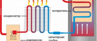
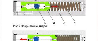
The operation of any door closer is based on the accumulation of energy in a compressed spring, after which it is used to smoothly close the door. The process of closing the door leaf is controlled using a hydraulic system, which makes it possible to make precise adjustments and ensure smooth operation of the mechanism.
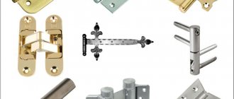
According to the type of installation, door closers can be:
- top position;
- floor
According to the principle of operation, they are divided into two groups:
- Devices with rack and pinion transmission. This is the most common type of mechanism. A lever system is used here. This solution is in good agreement with the linear force of the closer, due to which the process of opening and closing the door leaf occurs conveniently and smoothly. When opening the door, force is transmitted through the lever to the gear and rack. After which it activates a piston connected to a spring. When the blade is closed, the spring straightens and everything happens in the reverse order. The speed of closing the door depends on the amount of liquid that is pumped in different phases of the device’s operation. Special valves are used for adjustment.
- Mechanism with cam shaft. The difference from the previous device is that the force from the rod to the spring is transmitted through a roller and camshaft. When the cam rotates, a roller connected to the piston moves along its surface and activates the hydraulic system, after which the spring is compressed. This design allows you to choose the optimal cam shape, which allows the door to open and close more smoothly. Devices with this mechanism are more convenient to use.
Functions
| Menu 1 displays | Explanations | Possible settings | Factory settings |
| uA | Opening speed | 01 … 09 | 05 |
| uS | Closing speed | 01 … 05 | 04 |
| oH | Closing delay time (standard) | 00…60 s | 00 |
| or | Closing delay time with reduced opening | 00…60 s | 00 |
| oS | Closing delay time when the “Tolerance” contact sensor (KB) is turned on (key switch) | 00…60 s | 01 |
| ub | Acceleration, deceleration | 01 … 10 | 06 |
| uF | Shear displacement force | 01 … 10 | 10 |
| nE | Go to menu 2 | ↵ |
| Menu 2 displays | Explanations | Possible settings | Factory settings |
| Er | Indication of current faults | ▲ go to previous fault message ▼ go to next fault message. If CE appears, clear all current fault messages | — |
| oE | Fault recorder Display of the last fault message (max. 10 messages) | ▲ go to previous fault message ▼ go to next fault message. If CE appears, clear all current fault messages | — |
| di | Diagnostics (display of “trained” peripheral devices) | r0 / r1 without stopper / with stopper L0 / L1 / L2 / L3 without SIS / SIS 1 / SIS 2 / both SIS F0 / F1 / F2 / F3 without SIO / SIO 1 / SIO 2 / both SIOs S0 / S1 without / with antisub. contact A0 / A1 without/with battery -X leaf weight (x 100 kg) YZ + leaf weight (kg) | — |
| S.A. | Indication of operating time | C0 total number of door openings per 100 H0 number of operating hours per 4 hours FO number of self-tests | — |
| C.S. | Reset service message | ↵ turn off the service indicator LED | — |
| Fr/Fo | Engine release/motor connection | ↵ Engine release: Press key ↵. The door leaves move freely and the message Fo appears on the display. ↵ Connecting the motor: Press the ↵ key. The message Fr appears on the display. | |
| L.E. | Education | ↵ Start of training | |
| E.P. | Software version | ↵ Display of software version, e.g. Ft, 10 for version 1.0, DCU1-2M | |
| nE | Go to menu 3 |
| Menu 3 displays | Explanations | Possible settings | Factory settings |
| A1 | Response delay, internal contact sensor (KI) | 00 … 10 s** | 00 |
| A.A. | Response delay, external contact sensor (KA) | 00…10 s | 00 |
| A.C. | Emergency battery operation in case of power failure | 00 open when there is a power failure 01 close when there is a power failure* 02 no battery* | 00 |
| Cb | Final speed | 00 final speed = 0 01 constant final speed 4 cm/s | 00 |
| SL | Sluice or vestibule door | 00 master control 01 slave control (lock door)* 02 slave control (vestibule door)* | 00 |
| SF | Long press | 00 … 05 | 00 |
| HF | Dynamic increase in closing delay time | 00 disabled 01 enabled | 00 |
| SP | Language for operating mode indication | 00 German 01 English 02 French 03 Italian | 00 |
| E.F. | Number of sashes | 00 2-stage 01 1-st. | 00 |
| dt | Door type | 00 standard 01 linear, telescopic door 02 unoccupied 03 folding door | 00 |
| Ft | Functioning of inputs SIO 1 and SIO 2* | 00 stop when “opening”, after 4 minutes “closing” 01 Break Out, stop when “opening” and “closing” 02 not occupied 03 stop when “opening” 04 stop when “opening”, further movement at reduced speed | 00 |
| nE |
*Only for standard door controls (DCU1) **For FR door controls (DCU1-2M) always 00 sec
Setting the intermediate stroke
Usually the intermediate stroke is adjusted in unison with the main door stroke, but there are other options. For example, if you need to slightly reduce the speed halfway through the door closing. To do this, use the third adjusting bolt. This bolt serves to hold the door leaf in a certain position. For example, you need to add more closets to your apartment.
The screw can be adjusted so that the door remains open for a while, and only then begins to close.
Education
Close the door leaves before starting the “Teach” function. When using the rod stopper, before starting the “Training” mode, you must set the parameter rt = 4.
The “Teach” function in service mode determines the door travel parameters. The display program switch shows the following steps:
Training on installation of reduced opening width for escape doors (DCU1-2M)
To teach reduced opening widths, the user must submit in writing for the emergency evacuation route the prescribed width of the emergency evacuation route. Reduced opening width training is only permitted upon submission of this document. The specified reduced opening width must be no less than the prescribed width of the emergency escape route. A copy of the document must be provided to the service department or attached to the inspection log. The reduced opening width cannot be less than 30% of the opening width. The control device does not teach you to set the reduced opening width to a smaller value.
1. Before starting the training program on the control device, install a jumper between terminals 2 and 6. Run the training program. 2. When the L6 symbol appears on the program switch display, move the door to the required position with a reduced opening width. 3. Press the ↵ key. The door position is confirmed. 4. Press the ↵ key. The tutorial exits. Remove the jumper between terminals 2 and 6.
Check: 1. Switch to the “Automatic” AU program. 2. Simultaneously press the and keys to switch the door to the “Winter” mode.
3. Check the position with a reduced opening width with a tape measure when triggered or with a “reduced time for keeping the door constantly open.”
Source: Installation and Maintenance Instructions. Sliding door models: Slimdrive SL, Slimdrive SL-FR 2M, Econodrive EL and Econodrive EL-FR
Source
Methods for installing a door closer
Installing a door closer does not require special preparation, so you can cope with this task without any problems. Almost always, all the necessary parts and tools are included in the delivery kit. There are four ways to install a door closer; let’s look at them in more detail.
The easiest way to install a door closer is described in the annotation for it. It looks something like this: the lever arm is secured to the body of the device, then using the template that is attached to the annotation, the places for attaching the screws are marked, after which the screws are screwed in according to these markings. The main thing to remember is that you will also need to adjust the door closer. The second method of installing a door closer involves the following. It is necessary to attach the closer to the door so that its adjusting screws are facing the door hinges. Later, you need to fix the boot of the device with self-tapping screws, which are included in the kit with the closer. Do not forget that the “forearm” of the device lever must be such a length that it makes a right angle relative to the door. The shoulder is secured to the boot with self-tapping screws, after which you will again need to think about how to adjust the door closer. If you follow the third method of installing a parallel lever door closer, then you need to insert the lever of the device under the door block, and then fold it outside the room. In this case, the closer is attached using a bracket, which is also included in the delivery set. When installing the closer, make sure that the adjusting screws turn away from the hinges in the opposite direction.
It is important not to confuse anything during the installation process; otherwise, incorrect installation will lead to the fact that you will not be able to make the best adjustment of the door closer. There are door closers that use an adjustable spring. Installing such devices is not the most difficult: you just need to replace the hinge rod with the closer - and you’re done
The main thing is that the product matches exactly the weight of the door. If the door leaf is too heavy, and you could not find a suitable closer on sale, you need to install several, or a couple of closers.
Control
Access to service mode
Turning service mode on and off
➫ Press the service mode (1) and “Store closed” mode buttons (6) at the same time.
If no key is pressed within 5 minutes, the control unit switches to normal operation. Exceptions: in training mode, diagnostic mode and when the engine is turned off.
Service mode management
The service mode is started by the first function in menu 1 (uA function).
The service mode includes 4 menus, divided into individual functions. Different settings are possible for individual functions. After each change, the door leaves open and close. In service mode, the door maintains the current operating mode and closes and opens in accordance with it. Exception: LE and Fo functions. In service mode, the display program switch keys have the following purposes:
| Keyboard | Explanations |
| ▲ | go to previous function/setting or increase value |
| ▼ | move to next function/setting or decrease value |
| ↵ | confirm the function and go to settings / accept settings and return to the current menu |
| X | cancel and return to menu 1 (uA function) |
Types of closing/opening mechanisms
- The standard type of device is attached to the door leaf, and the rod that ensures closing is attached to the frame.
- With a sliding rod - they do not have “knees”, like standard devices, and look more aesthetically pleasing. There are also similar models, but with an open position lock.
Based on the type of fastening, they are divided into top and floor. If overhead closers are installed on doors that open only in one direction - “towards you” or “from you”, then floor closers are installed on doors that open in both directions. In addition, floor mechanisms can withstand the greatest weight (up to 300 kg). Working structures can be hidden, and when the door is closed they are not visible.
The mechanisms themselves can be adjusted according to the strength and speed of closing. On some models you can also adjust the “latching” function.
Functions
| Menu 1 displays | Explanations | Possible settings | Factory settings |
| uA | Opening speed | 01 … 09 | 05 |
| uS | Closing speed | 01 … 05 | 04 |
| oH | Closing delay time (standard) | 00…60 s | 00 |
| or | Closing delay time with reduced opening | 00…60 s | 00 |
| oS | Closing delay time when the “Tolerance” contact sensor (KB) is turned on (key switch) | 00…60 s | 01 |
| ub | Acceleration, deceleration | 01 … 10 | 06 |
| uF | Shear displacement force | 01 … 10 | 10 |
| nE | Go to menu 2 | ↵ |
| Menu 2 displays | Explanations | Possible settings | Factory settings |
| Er | Indication of current faults | ▲ go to previous fault message ▼ go to next fault message. If CE appears, clear all current fault messages | — |
| oE | Fault recorder Display of the last fault message (max. 10 messages) | ▲ go to previous fault message ▼ go to next fault message. If CE appears, clear all current fault messages | — |
| di | Diagnostics (display of “trained” peripheral devices) | r0 / r1 without stopper / with stopper L0 / L1 / L2 / L3 without SIS / SIS 1 / SIS 2 / both SIS F0 / F1 / F2 / F3 without SIO / SIO 1 / SIO 2 / both SIOs S0 / S1 without / with antisub. contact A0 / A1 without/with battery -X leaf weight (x 100 kg) YZ + leaf weight (kg) | — |
| S.A. | Indication of operating time | C0 total number of door openings per 100 H0 number of operating hours per 4 hours FO number of self-tests | — |
| C.S. | Reset service message | ↵ turn off the service indicator LED | — |
| Fr/Fo | Engine release/motor connection | ↵ Engine release: Press key ↵. The door leaves move freely and the message Fo appears on the display. ↵ Connecting the motor: Press the ↵ key. The message Fr appears on the display. | |
| L.E. | Education | ↵ Start of training | |
| E.P. | Software version | ↵ Display of software version, e.g. Ft, 10 for version 1.0, DCU1-2M | |
| nE | Go to menu 3 |
| Menu 3 displays | Explanations | Possible settings | Factory settings |
| A1 | Response delay, internal contact sensor (KI) | 00 … 10 s** | 00 |
| A.A. | Response delay, external contact sensor (KA) | 00…10 s | 00 |
| A.C. | Emergency battery operation in case of power failure | 00 open when there is a power failure 01 close when there is a power failure* 02 no battery* | 00 |
| Cb | Final speed | 00 final speed = 0 01 constant final speed 4 cm/s | 00 |
| SL | Sluice or vestibule door | 00 master control 01 slave control (lock door)* 02 slave control (vestibule door)* | 00 |
| SF | Long press | 00 … 05 | 00 |
| HF | Dynamic increase in closing delay time | 00 disabled 01 enabled | 00 |
| SP | Language for operating mode indication | 00 German 01 English 02 French 03 Italian | 00 |
| E.F. | Number of sashes | 00 2-stage 01 1-st. | 00 |
| dt | Door type | 00 standard 01 linear, telescopic door 02 unoccupied 03 folding door | 00 |
| Ft | Functioning of inputs SIO 1 and SIO 2* | 00 stop when “opening”, after 4 minutes “closing” 01 Break Out, stop when “opening” and “closing” 02 not occupied 03 stop when “opening” 04 stop when “opening”, further movement at reduced speed | 00 |
| nE |
*Only for standard door controls (DCU1) **For FR door controls (DCU1-2M) always 00 sec
Instructions for self-adjustment of the device
After installing the door leaf, it is necessary to install a closer. It must be located inside the building so as not to become contaminated by street dust and dirt. For installation you will need a ruler, a simple pencil, a drill and a screwdriver. And also a stool if the box is too big.
The fastening device is located in the same set with the door closer. The kit also includes instructions for easy DIY installation. When mounting, first fix the housing, then attach the lever rod.
Self-adjustment of the door closer begins with finding two adjusting screws. One sets the main door movement from 180 to 15 degrees, and the other the final stages.
Device installation steps:
You cannot make more than two turns from the original location, so as not to break the device.
Education
Close the door leaves before starting the “Teach” function. When using the rod stopper, before starting the “Training” mode, you must set the parameter rt = 4.
The “Teach” function in service mode determines the door travel parameters. The display program switch shows the following steps:
| Message | Explanations | Possible settings |
| L0 | Launch | — |
| L1 | Checking the selsyndatchik | — |
| L3 | Opening width | — |
| L2 | Toothed belt stopper | — |
| L8 | Friction force | — |
| L4 | Sash weight | — |
| L6 | Reduced opening width | ➫ Move the door to the required position. ➫ Press the ↵ key. The setting is confirmed. - or - Automatic confirmation after 30 seconds. |
| L7 | End | ➫ Press the ↵ key. The settings are accepted. |
| EL | Error during training |
Training on installation of reduced opening width for escape doors (DCU1-2M)
To teach reduced opening widths, the user must submit in writing for the emergency evacuation route the prescribed width of the emergency evacuation route. Reduced opening width training is only permitted upon submission of this document. The specified reduced opening width must be no less than the prescribed width of the emergency escape route. A copy of the document must be provided to the service department or attached to the inspection log. The reduced opening width cannot be less than 30% of the opening width. The control device does not teach you to set the reduced opening width to a smaller value.
1. Before starting the training program on the control device, install a jumper between terminals 2 and 6. Run the training program. 2. When the L6 symbol appears on the program switch display, move the door to the required position with a reduced opening width. 3. Press the ↵ key. The door position is confirmed. 4. Press the ↵ key. The tutorial exits. Remove the jumper between terminals 2 and 6.
Check: 1. Switch to the “Automatic” AU program. 2. Simultaneously press the and keys to switch the door to the “Winter” mode.
3. Check the position with a reduced opening width with a tape measure when triggered or with a “reduced time for keeping the door constantly open.”
Source: Installation and Maintenance Instructions. Sliding door models: Slimdrive SL, Slimdrive SL-FR 2M, Econodrive EL and Econodrive EL-FR
How to adjust the door closer after installation
The function of a modern closing device is no different from the operation of the previous “antediluvian” springs, which were previously installed at the entrance to the front doors of residential buildings, organizations, and shops. Their big disadvantage was the sharp slamming of the door with a loud knock. Such a rapid closing of the front door was inconvenient and quite dangerous, especially for children, who could easily get their hands pinched. A modern door closer, its installation and adjustment, solve the problem of noise in the entrance, forcing the door structure to work in the prescribed mode.
The main working mechanism of any closer is a spring-loaded hydraulic shock absorber. Oil circulates from one chamber to another thanks to a system of valves that set the valve to move in different directions. The viscosity of the oil composition ensures smooth closing and opening of the door.
The closing device is installed indoors so that it cannot be removed from the outside. This protects the mechanism from dirt, dust, and also creates additional safety for residents. For installation you need instructions and tools:
- screwdriver;
- ruler;
- drill;
- pencil for marking.
The fasteners are included in the kit, which the manufacturers supplement with installation templates, which display all the components of the mechanism in full size and the location of the holes for fastening. Installation begins with fastening the housing, which is then connected to the traction lever. All steps are described in detail in the instructions, following which the installation is carried out quickly and without problems.
The device parameters, as well as adjustment methods, depend on the type of closing mechanism. There are two of them.
- Cam. The cam, as the main moving part, moves thanks to the rollers and presses on the spring, which smoothly guides the blade. The systems work well on lightweight doors.
- Serrated. The movement occurs due to a gear that transfers energy to a spring. The mechanism can be used for sashes with significant weight.
Depending on the location and method of installation, door closers are classified into one of three types.
- Floor. The name speaks for itself, the system is adjustable from below. The installation is carried out together with the installation of the door frame, planning in advance. The systems are used at the entrances to large buildings.
- Overhead. This is the most commonly used automatic closer. The device is installed on top, connecting the box and the canvas itself. Such mechanisms are always used for metal doors in residential buildings because they are easy to use and maintain.
- Hidden. This type of mechanism is rare. It is mounted directly into the door hinges or into the end of the door frame. Allows you not to disturb the interior of the room, is expensive, and has an increased degree of safety.
Selecting the door speed
After installation is completed, it is necessary to adjust the door closer so that the speed of door movement is most convenient during operation. Each device is equipped with special screws for adjusting the blade stroke. If it moves too quickly, it will be enough to turn the screw clockwise ½ turn. If the movement is too slow, turn the screw counterclockwise the same half turn.
Adjustment is carried out by trial until the speed is optimal. High closing speed is good for limiting the entry of strangers, insects and cold air. But for interior doors or kitchen cabinet doors, they usually set the movement to slow. This adjustment technique applies to all types of closers. The essence of the process is that the more the screws are tightened, the slower the oil flows from one cavity to another, the slower the system operates.
Installing the exhaust
When setting up the closer, special attention should be paid to adjusting the aftershock. This is the speed at which the door travels its final trajectory. When the high-speed slam is selected, it may slam shut with a loud noise, which destroys the box. Therefore, it is necessary to adjust the door closer so that the closing speed is low.
Setting the closing speed is similar to adjusting the general speed with the difference that the closing speed is provided only on the last 15-25 cm of the trajectory of the outer edge of the door. The higher the speed is set, the stronger the force of impact of the sash on the jamb. When choosing the passage speed at the end of the movement path, it is optimal to set the average value when closing is relatively fast, but without hitting the door frame. The aftershock is set by turning screw No. 2, which will adjust the movement of the canvas in such a way that the movement will first slow down, and then it will completely adjoin the jamb.
Calibrating the open position
In some cases, it is required that the doors be held open, for example, when furniture is being transported, or parents call a doctor to see their child, but there is no intercom. Adjustment of the “open door” mode in the door closer system is provided and performed simply.
Many models of top-mounted systems have a “hold open” option. To set the mode, you need to set the door at 90° and attach a special lock that will keep the door open as long as needed. If you open the sash to a different degree, the system will work without holding. When the need for open doors disappears, you need to pull the sash towards you, and the setting will be removed automatically.
Instructions for setting up the door closer with your own hands, features of adjusting some models on the door
A door closer is a mechanism that is designed to reliably close entrance doors. It presses the blade against the seals along the contour or creates the necessary force sufficient to trigger the lock latch. The door can close abruptly and with a sound, or smoothly and without making sounds, and can also pause.
Adjusting the door closer is a mandatory measure to extend the service life and maintain the performance characteristics of the mechanism.
It is subject to constant loads; frequent closing and opening of the door leads to imbalance of the elements of the device, and therefore requires periodic maintenance and repair, both for preventive purposes and if necessary.
Limitations in adjusting the closer
In order not to damage the mechanism of the device, it is necessary to observe some restrictions:
- You cannot turn the screw more than two turns from the starting point, or oil loss will occur, all this will negatively affect the performance of the mechanism;
- During installation, distortions should not be allowed, otherwise the product will quickly become unusable;
- When the door is not fully open, you should not prop it up with foreign objects; you must use a special function;
- It is not allowed to place heavy objects on the door leaf, otherwise this may lead to a skew of the constructed diagonal.
Compliance with these rules will allow you to regulate the closer in a quality and timely manner, extending its service life using all its functionality.
When adjustment is needed
Experts recommend adjusting the mechanism immediately after installing the door closer, and not only during operation of the doors. Inspection and correction of minor problems is carried out at least 2 times a year, with frequent fluctuations in temperature indoors and outdoors - more often. This is due to the fact that the lubricating fluid depends on the temperature parameters of the environment and affects the parts of the closer.
Carrying out seasonal adjustments is a regular part of maintenance.
With large temperature fluctuations, the front door mechanism quickly wears out and becomes faulty. Therefore, it is better, when the first signs of damage to the closer occur, to pull it to the desired position, check the tightness to detect oil leaks and eliminate the malfunction.
In case of complex breakdowns, adjusting the door closer on your own is ineffective. Experts recommend carrying out repair work or replacing it.
If problems arise with the device settings, the parameters are adjusted. This procedure is performed if the mechanism turns out to be difficult to open, as well as with a door that closes quickly and sharply or takes a long time to pull.
Device types
The mechanism controls the movement of the web (closer). It sets the movement mode: speeds up or slows down the closing process, gives softness and ease to the sliding of the sash. There are several operating principles.
In practice, two types are used:
- The sliding rod operates the spring and piston system. One piston opens, the other brakes. The sliding type design is compact and reliable, suitable for lightweight doors.
- With a lever-type gear transmission - the most common class of locking structures. A reliable combination of spring rod and gear allows you to install devices on massive doors.
The main requirement for choosing a door closing regulator is that it must correspond to its parameters; the more massive the door leaf, the more powerful the door closer is needed.
Based on the location of the control units on the door, the following groups are distinguished:
- upper;
- floor mounted systems;
- hidden.
Upper. A widespread class of door closers. The combination of low price and reliable operation makes them popular among the population. They are installed at the top of the sash, which is very practical during installation. Manufacturers produce special oil-filled devices for external doors, adapted for use in hot or frosty climates.
Floor holders. They have proven themselves well in office premises, shopping centers, banks, where there are increased requirements for the appearance of doors. Flooring systems are built into the flooring and are practically invisible to visitors. Sliding type regulator designs are used and are designed for doors weighing up to 100 kg.
Internal devices. The devices are indispensable where careful cosmetic finishing and an impeccable front façade are required.
- Small sliding type design, mounted inside the door frame or leaf.
- The loop closer is a compact device. The range of application is limited: do not install on heavy doors; wears out quickly; special precision of installation on the doorway is required.
How to do it right
Adjusting the door closer, the instructions for which provide requirements for installation and adjustment of the mechanism, consists of the following steps:
The procedure requires a minimum of tools - a screwdriver.
How to do it yourself
In order to understand how to adjust the door closer, you need to understand the design features of the device.
The mechanism consists of the following components and parts:
When working, you must adhere to the strict rules of the instructions for installing and adjusting the device, which boils down to spring tension.
On the body of the closer, when adjusting, there are 2 adjusting screws, which are responsible for the speed of movement of the blade and the speed of closing. The first screw regulates the main stroke of the door from full opening 180° to 15°, and the second - its final closing. Some models also have a third screw to change the overall force.
The procedure is performed as follows:
Options
When adjusting the door closer with your own hands, significant attention is paid to such parameters as:
Closing speed is how quickly or slowly the doors close. The closing force allows you to adjust the device so that in the last 7-15° the speed increases and the lock latches.
To protect the door block from damage during sudden openings, the opening speed is adjusted. For this purpose, closers with a braking function, such as a “wind brake,” are installed on the entrance doors of buildings.
Structures and traction device
The main design element of a door closer is a spring that pushes the lever. There are two types of devices based on the method of transmitting force from a spring to a lever:
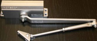
- With lever pull. Such models have a characteristic appearance - levers stick out perpendicular to the surface of the door leaf. The same closers are also called with a knee or articulated rod. The design works reliably, but the protruding arms are unattractive and easy to break if desired. There is another drawback: as the door opens, more and more force is required. For children and older people this can be a problem.
With linkage - With sliding channel. In these models, the lever is located parallel to the door leaf, which provides a more attractive appearance. Another plus: when opening the door by 30°, the force for further opening becomes much lower. Doors equipped with such door closers can be easily opened by both children and the elderly.
With sliding channel
Both of these types consist of two parts: a housing in which the spring is hidden and a force-transmitting mechanism and lever. They are mounted at the top of the door: one part on the leaf, the second on the frame. Which one goes where depends on the direction of opening. If the doors open “pull”, a housing with a mechanism is installed on the door leaf; when opening “pull,” a lever is attached. The photo shows a lever type closer, but similar installation rules apply to models with a sliding channel.
Installing a door closer depending on the opening direction
As you understand, they are not suitable for all types of doors - it is problematic to install them on glass ones. There is another design for them - floor-mounted. The housing with the mechanism is mounted on the floor, only the holder plate protrudes from above. A similar holder is installed at the top, but the mechanism is not always there, only for heavy door leaves.
Floor closer for glass doors
By the way, there are floor models for wooden and metal doors. They also have a linkage or sliding channel transmission. They are less conspicuous, but with this arrangement they are more often damaged.
Floor closer for glass doors
Do-it-yourself installation of interior doors is described here.
Features of some models
The most common door closers among users are “Dorma” TS-68, “Diplomat”, “GEZE” TS 4000. Each model has its own characteristics of regulating such devices.
"Dorma" TS-68 is a classic top-mounted model. Its peculiarity is that the mechanism is equipped with a special lever to change the door locking force.
The Diplomat model is characterized by simple installation and maintenance of the mechanism. Adjusting the door closer includes the stages of spring tension and opening and closing adjustments. Some modifications of the “Diplomat” do not have a clap setting. The devices operate on the principle of hydromechanics.
"GEZE" TS 4000 is a popular top door mechanism model among users. The closer can adjust the opening damping, adjust the thermostable closing speed at the front and the final closing using a lever rod.
Source
Types of door closers
To understand the configuration issue, you first need to familiarize yourself with its classification.
They come in 2 types:
- Cam slide. It is used for smooth closing of blocks in lightweight structures.
- Toothed lever. Used for heavy fabric with codes, considered the most common.
According to the installation method, closers are divided into the following types:
- Top or overhead. Installation is carried out from above the structure.
- Floor-standing. Often attached to the bottom of blocks.
- Hidden or framed. They are located inside the frame or in the floor.
Tips from experts on repairing door closers
Home adjustment of the door closer is subject to certain restrictions. They are needed for long and efficient operation. It is necessary not to load the doors with heavy things, because the weight will cause the structure to warp and breakage may occur. It is not recommended to prop up open sashes, because there is a “hold open” option for this.
When mounting, it is important not to twist the screws more than 2 turns from the original position. This is necessary to prevent the oil composition from leaking out. If the oil leaks, the device will cease to perform its main function, and repairing the problem is not easy.
It is also important to control distortions during surgery. If distortions appear during installation, then there will certainly be breakdowns during operation.
Many craftsmen are interested in how to remove the device when repairing it - in the reverse order: first remove the lever, and then unscrew the housing.
Before starting repairs, determine the cause of the problem. Main reasons:
Most often, two types of breakdowns occur: oil leakage or rod deformation:
1 If the rod is deformed, you need to check the material from which it is made. If it is a regular steel alloy, then it is susceptible to corrosion. The rusted areas are cleaned and lubricated with a special anti-rust agent. If a break appears, you will need to work with a welding machine, and finally clean the seams well. When bending or bending, everything is straightened with a hammer. But you should use the hammer carefully so that the parts do not break due to overload. If there is too much distortion or rust, then a new part is purchased and replaced.
2 Leakage of oil solution occurs due to cracks. If everything leaks, the structure will have to be replaced with a new one. Because the device will become an ordinary spring and will slam very loudly without the possibility of regulation. The fault must be fixed as soon as possible so as not to lead to a complete replacement of the equipment. If there is a small crack in the body and the oil has not had time to completely drain out, then the damaged area is sealed with hermetic putty. If there is a large hole and significant oil leakage, the sealant will be useless - a hollow replacement will be required.
Some manufacturers may not add enough oil to the product body, which is why a slow closing rate is not achieved. To eliminate the malfunction, it will be necessary to refill through the screw holes with shock absorbers or solutions of motor oils with a synthetic composition.