Comfortable, cozy and warm conditions at home depend on the correct installation of windows, but before carrying out installation work on PVC windows, you need to take into account the layout of the room and take measurements.
Standard sizes of modern windows are divided into subtypes with their own characteristics; for this reason, the master initially needs to calculate the proportions of the window frames and prepare a sectional drawing. The article provides a detailed analysis of the dimensions of typical double-glazed windows and options for correct measurement and installation process.
Specification of elements for filling doorways: GOST requirements
During the construction of any type of building, one of the main documents establishing the design plan is the specification form for the elements of filling the openings. It indicates a list of necessary items, their design features, sizes and other characteristics. There are even separate GOST standards on this subject; they primarily concern the rules for drawing up specifications and the principle of submitting the necessary information.
What it is
For a person who has heard such a term for the first time, it will be interesting to find out in more detail what the specification of elements for filling doorways is. At its core, it is a kind of document, or rather, part of the design documentation for any building. It complements the drawn up drawings and demonstrates the names and models of those elements with which it is planned to fill the doorways in the future. In other words, it is a list of structures and their individual parts that are required to complete a construction project. Thanks to the specification, you can estimate the construction budget and see a more accurate plan for the final result.
When performing independent work on the construction of a building on a private plot, there is no need to draw up a specification. You can make do with approximate calculations and purchase everything you need during the interior finishing work.
The rules for compiling this list are determined by GOST. The same requirements also apply to the specifications for window openings, niches and partitions with gaps.
Specification of openings with door opening type
What is a door leaf?
When we talk about doors, we usually mean a door with an already installed structure. This is logical, but not always true, for example, when we need to understand how the canvas differs from the door. The leaf is a rectangular structure that is the main part of the door, but without an installed frame, trim, hinges, etc.
General requirements according to GOST
In order for the specification form for opening filling elements to comply with GOST, it is necessary to carefully study standard number 21.101. This describes general provisions regarding the rules for implementing design documentation during the construction of a building. It is imperative to draw up detailed drawings, which should be accompanied by a specification. The corresponding designations allow you to more accurately present a picture of the future structure.
You should also refer to GOST 21.501. This paragraph explains the rules for drawing up the drawings themselves. Both standards contain many subclauses. As for the doorways themselves, they are mentioned here separately. When performing specifications on drawings, it is important to comply with special requirements regarding the dimensions of the table. Specific dimensions for columns and spacing for rows are provided here.
In general, for a person who does not have special skills or education in this field, it will be quite difficult in a short time to understand all the intricacies of drawing up project documentation, including specifications.
GOST 21.501 - a document regulating the rules for drawing up specifications
What to include in the diagram
According to GOST, there is a pre-designed form intended for filling out the specification. It takes into account the presence of all the necessary columns for entering product parameters. There is a category of mandatory names that cannot be removed from the form. In some cases, they are quite sufficient for a basic description of the situation. If you need to indicate any specific data, it is possible to add auxiliary columns for this type of information.
In general, the following parameters are entered into the diagram:
- item number;
- product name;
- number of units.
Additionally, specific units of measurement, the weight of items recorded in the specification, or a specific brand or model may be indicated.
For doorways, the specification list usually includes only a few components. First of all, this is, of course, the door leaf and frame or arch. In addition, additional elements, thresholds and platbands, as well as other elements of the design of the opening, can be attributed to them. In some cases, the inventory also contains individual fragments of the canvas itself. For example, it could be glass and stained glass. Protective structures such as grilles and roller shutters must also be recorded on the form.
An example of a door specification in accordance with GOST
Note box
In addition to the main provisions, GOST requires the presence of an additional column in the specification form - “Notes”. In this section, brief notes can be made regarding important design points that are not included in the general list of columns. These primarily include:
- door dimensions;
- dimensions of the opening framing structure;
- the material from which the filling element is made;
- cost of goods;
- total weight.
In addition to the specification, ideally there should be a detailed building plan with drawings in several projections. The rules for their implementation are also established by GOST.
The specification allows you to more fully cover the list of upcoming work and indicates a list of necessary materials to complete construction and design openings. This is very convenient when you need to provide an estimate for each item.
We recommend watching the video:
Determining the depth of the opening
To do this, you will need to measure the thickness of the wall on which the door is located. This will be the depth of the opening. The measurement should be taken in three parts: top, middle and bottom on both walls. This painstaking exercise is necessary to determine the widest point of the wall.
If the old door was not disassembled, you need to measure the dimensions of the frame and the wall (thickness) if it protrudes beyond the frame. It is best to use the services of a professional to correctly measure the three main parameters. With his combined knowledge, the installer will carry out impeccable measurements and give practical advice on choosing a standard or non-standard interior door.
MAIN SIZES AND GRADES
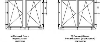
1.1. Windows and balcony doors are manufactured according to this standard with separate sashes and door leaves.
1.2. The overall dimensions of windows and balcony doors and the dimensions of the openings for them must correspond: for residential buildings - indicated in Fig. 1 and Appendix 1; for public buildings - indicated on the drawing. 2 and in Appendix 2.
Windows and balcony doors shown in the drawing. 1 can also be used for public buildings.
1.3. Windows sizes 9-13.5; 12-13.5; 15-13.5; 18-13.5 and 21-13.5 modules (module M = 100 mm) for filling openings in walls made of non-modular bricks of facing masonry, at the request of the consumer, must be manufactured with a width of 80 mm greater than that indicated in the drawing. 1 by increasing the width of the wide sashes, and a window with dimensions of 15-6 modules is 70 mm less wide than indicated in the drawing. 1, in this case the marking is changed accordingly to 9-14; 12-14; 15-14; 18-14; 21-14 and 15-5.
1.4. At the request of consumers, single-leaf windows and balcony doors, incl. with window sashes and transoms, should also be made on the left, and multi-leaf windows with an asymmetrical pattern - in a negative image.
1.5. The following structure of the symbol (brand) of windows and balcony doors is established:
Examples of symbols:
Right window type RS for an opening 15 dm high and 9 dm wide:
ORS15-9 GOST 16289-86
ORS15-9L GOST 16289-86
Window type RS for an opening 15 dm high and 13.5 dm wide, with a sash:
ORS15-13.5 GOST 16289-86
The same, for an opening 18 inches high and 18 inches wide, with an asymmetrical pattern (option B):
ORS18-18V GOST 16289-86
The same, in a negative image:
ORS18-18VN GOST 16289-86
Right balcony door type RS for an opening with a height of 22 and a width of 7.5 dm:
BRS22-7.5 GOST 16289-86
BRS22-7.5 L GOST 16289-86
Convenient sizes of interior doors
It is easier to determine the height of doorways. Everything here is tied up at the height of the ceiling. And the choice is small - only two options - 2.1 m and 2.3 m. But what about the width? There are more opportunities here. In general, there are certain recommendations that relate to the minimum door sizes. Namely doors, and not openings under them. The opening should be 70-100 mm wider. So, the dimensions of interior doors must be no less than the specified width:
- In technical rooms (storage rooms, bathrooms, baths and toilets) the recommended width of the canvas is 600 mm.
- For kitchens the minimum is 700 mm.
- For living rooms, at least 800 mm is recommended.
SNiP has recommendations on minimum door sizes.
Of course, you can increase the size of interior doors if the doorway allows. Reduce at your own discretion. But the narrowest door leaf that can be found on sale is 550 cm, and even then it is inconvenient for obese people. In the kitchen and room where gas equipment may be located, the width of doorways is dictated and controlled by the fire safety service. So it won't be possible to do it anymore. Wider is possible.
As for residential premises, openings can also be made for double doors. That is, up to the maximum permitted in GOST 1.5 meters. There may be wider ones, but this is no longer standard. In a wide opening you can install not only conventional swing models, but also sliding or folding ones. But large and wide doors look good in large areas. So the recommended sizes of interior doors were chosen for a reason. They took into account the not too large rooms in our homes.
CONSTRUCTION REQUIREMENTS
2.1. Windows and balcony doors must be manufactured in accordance with the requirements of GOST 23166-78 and this standard according to working drawings approved in the prescribed manner.
2.2. The design, shape, main dimensions and brands of windows and balcony doors for residential buildings must correspond to those indicated in the drawing. 3-6, section sizes - as shown in Fig. 7-15; for public buildings on the devil. 16-22, section sizes - as shown in Fig. 23-32.
2.3. Dimensions on general views of windows and balcony doors are given in the light, on the outer sides of the sashes, vents, transoms and door leaves and on the outer sides of the frames.
Single and double doors
Double doors with two leaves will look impressive in the design. The width of the products depends on the model and parameters of the living room passage. Parameters for such gates are sometimes taken with an increase of 1.5-2.
The standard dimensions of double systems with a box are 120-150 cm, which allows the installation of full-fledged double-leaf structures. The width of double doors is 1-1.4 m.
For minimum dimensions, double doors can be offered with a fixed leaf of ½ or 1/3 standard width (for example, versions with one and a half leaf). The other part of the canvas will be completed. With an optimal opening width, identical sashes are placed, which increases aesthetics and maneuverability.
TYPES, SIZES AND GRANDS
1.1. Windows and balcony doors manufactured according to this standard are divided into types:
C - with paired doors and door leaves;
R - with separate doors and leaves.
1.2. The overall dimensions of windows, balcony doors and the dimensions of openings for them must correspond to:
for residential buildings - indicated on the drawing. 1 and Appendix 1;
for public buildings - indicated on the drawing. 2 and in Appendix 2.
Windows and balcony doors shown in the drawing. 1 can also be used for public buildings.
1.3. Windows sizes 9-13.5; 12-13.5; 15-13.5; 18-13.5 and 21-13.5 modules (module M-100 mm) for filling openings in walls made of non-modular bricks of facing masonry, at the request of the consumer, it is allowed to produce a width of 80 mm more than specified, due to the increase in wide sashes, and the window dimensions 15-6 modules - 70 mm less than specified in width, while the marking is changed accordingly to 9-14; 12-14; 15-14; 18-14; 21-14 and 15-5.
1.4. For residential buildings erected in climatic region IV, it is allowed to use windows with a narrow sash (without a window).
1.5. At the request of consumers, single-leaf windows and balcony doors, incl. with window sashes and transoms, should also be made on the left, and multi-leaf windows with an asymmetrical pattern - in a negative image.
1.6. The following structure of the symbol (brand) of windows and balcony doors is established:
At the end of the brand of windows and balcony doors with single glazing, before the standard designation, add the number 1 through a dash.
An example of a symbol for a type C window for an opening 15 inches high and 9 inches wide, with right-hand hinged sashes:
OS 15-9 GOST 11214-86
The same, with the left hinged doors:
OS 15-9L GOST 11214-86
Right balcony door type C for an opening 22 dm high and 9 dm wide:
BS 22-9 GOST 11214-86
The same, type P window for an opening 18 dm high and 18 dm wide, with an asymmetrical window pattern (option B):
OR 18-18V GOST 11214-86
The same, in a negative image:
OR 18-18VN GOST 11214-86
The same, type C windows for an opening with a height of 15 and a width of 13.5 dm, with a window sash:
OS 15-13.5 GOST 11214-86
The same for the right balcony door type C for an opening 22 inches high and 7.5 inches wide with a right door hinge:
BS 22-7.5 GOST 11214-86
The same for the left balcony door:
BS 22-7.5L GOST 11214-86
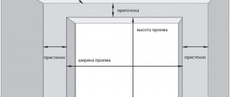
Opening
Before talking directly about doors, let's define general concepts. One of these, the interior door opening size, is used when referring to the opening in the building or passage in the wall where the door will be inserted. There are also three more indicators, indicated in the figure by dimensional characteristics (height and width).
Why should the opening be larger than a door with a frame (frame, jamb)
Three reasons:
- The opening is needed for strictly vertical installation of the box. Although GOST specifically prescribes the dimensions of doorways, not all passages are completely vertical and square, and the floors are even. With the extra space, the door can be installed or aligned perfectly.
- Not all doors are the same size. They may vary depending on the manufacturer. But if the opening is left exactly to the size of the door with the frame, it will be impossible to position the door without room for adjustment.
- It is important to leave room for the wall to expand and contract. Yes, the wall gets bigger and smaller as the seasons change. It absorbs moisture when it's humid outside and shrinks when the temperature and humidity levels drop. We are talking about small sizes: 1.5 – 2 mm. But this will be enough to prevent a perfectly fitted door one fine morning from starting to jam, rubbing the jamb, and the lock or latch no longer locking properly.
CONSTRUCTION REQUIREMENTS
2.1. Windows and balcony doors must be manufactured in accordance with the requirements of GOST 23166-78, the requirements of this standard and according to working drawings approved in the prescribed manner.
2.2. The design, shape, main dimensions and brands of windows and balcony doors of type C for residential buildings must correspond to those indicated in the drawing. 3-5, for public buildings - to hell. 6-11, and the dimensions of the sections of parts and vestibules are on the devil. 12-23.
2.3. The design, shape, main dimensions and brands of windows and balcony doors of type P for residential buildings must correspond to those indicated in the drawing. 24-27, for public buildings - to hell. 37-43, and the dimensions of the sections of parts and vestibules for residential buildings are on the devil. 28-36, public buildings - to hell. 44-53.
2.4. Dimensions on general views of windows and balcony doors are given in light on the outer sides of the sashes, transoms, vents, door leaves and on the outer sides of the frames.
The drawings given in this standard indicate the dimensions of unpainted parts and products in millimeters.
2.5. To drain rainwater, slots with a width of 12 mm are made in the lower bars of frames and in horizontal imposts of windows and balcony doors of type C, and holes with a diameter of 10 mm are drilled in windows and balcony doors of type P, located under wide sashes, balcony door leaves and transoms at a distance 50 mm from the vertical bars of boxes and imposts, and under window and narrow sashes - one slot or one hole in the middle.
What other dimensions need to be taken into account during installation?
The general appearance of the structure, including the metal entrance door, depends on compliance with simple rules.
- The mounting hole for the box should be about 10 cm wider than the tray; in extreme cases, it can be narrowed. This is much simpler than expansion, and after installing the trim you won't notice anything.
- It is prohibited to adjoin the opening space to an adjacent wall. The distance must be at least 10 cm.
- Voids under slabs are formed when the depth of the hole does not correspond to the thickness of the workpiece and when the wall is uneven. The latter must be corrected before installation work begins.
- The thickness of the sheathing is no more than 0.8 cm, so the distance from the wall to the floor covering should not be greater.
Knowing the standard sizes of interior door systems greatly simplifies their selection and installation. It is important not to make mistakes when taking measurements and choosing a product, otherwise it is difficult to calculate how much additional money will be spent on correcting errors.
TYPES, SIZES AND GRANDS
1.1. Windows and balcony doors manufactured according to this standard are divided into types:
C - with paired doors and door leaves;
R - with separate doors and leaves.
1.2. The overall dimensions of windows, balcony doors and the dimensions of openings for them must correspond to:
for residential buildings - indicated on the drawing. 1 and Appendix 1;
for public buildings - indicated on the drawing. 2 and in Appendix 2.
Windows and balcony doors shown in the drawing. 1 can also be used for public buildings.
1.3. Windows sizes 9-13.5; 12-13.5; 15-13.5; 18-13.5 and 21-13.5 modules (module M-100 mm) for filling openings in walls made of non-modular bricks of facing masonry, at the request of the consumer, it is allowed to produce a width of 80 mm more than specified, due to the increase in wide sashes, and the window dimensions 15-6 modules - 70 mm less than specified in width, while the marking is changed accordingly to 9-14; 12-14; 15-14; 18-14; 21-14 and 15-5.
1.4. For residential buildings erected in climatic region IV, it is allowed to use windows with a narrow sash (without a window).
1.5. At the request of consumers, single-leaf windows and balcony doors, incl. with window sashes and transoms, should also be made on the left, and multi-leaf windows with an asymmetrical pattern - in a negative image.
1.6. The following structure of the symbol (brand) of windows and balcony doors is established:
At the end of the brand of windows and balcony doors with single glazing, before the standard designation, add the number 1 through a dash.
An example of a symbol for a type C window for an opening 15 inches high and 9 inches wide, with right-hand hinged sashes:
OS 15-9 GOST 11214-86
The same, with the left hinged doors:
OS 15-9L GOST 11214-86
Right balcony door type C for an opening 22 dm high and 9 dm wide:
BS 22-9 GOST 11214-86
The same, type P window for an opening 18 dm high and 18 dm wide, with an asymmetrical window pattern (option B):
OR 18-18V GOST 11214-86
The same, in a negative image:
OR 18-18VN GOST 11214-86
The same, type C windows for an opening with a height of 15 and a width of 13.5 dm, with a window sash:
OS 15-13.5 GOST 11214-86
The same for the right balcony door type C for an opening 22 inches high and 7.5 inches wide with a right door hinge:
BS 22-7.5 GOST 11214-86
The same for the left balcony door:
BS 22-7.5L GOST 11214-86
The nuances of correct opening measurement
In some cases, it becomes necessary to take measurements yourself when purchasing an interior door. This happens if the house or apartment is located at a great distance from the place where the doors were ordered, in another city.
Self-measurement is also carried out in cases where there is no time to wait for a surveyor to visit or it is more convenient for the customer to carry out the measurements themselves. Regardless of the reason, this action must be performed as accurately as possible so that the selected door fits tightly into the existing opening without the need for adjustment.
This means that the height, width and thickness of the internal door leaf should be as close as possible to the corresponding parameters of the opening. To make the correct measurement, you should follow the following rules.
Opening to living rooms
The size of the opening for a canvas of 80 cm is 88.5 x 205.5 cm. These are the optimal values for the finished opening. Before installation, you need to know the material of the box and the canvas. If the door leaf is made of solid wood, the thickness of the frame can be much greater: the weight of the door also needs to be taken into account.
It is necessary to take into account the presence of a threshold or mounting strip that covers the junction of several floor coverings just below the doors. This value must be added to the height of the opening. The width of the canvas is 800 mm and the dimensions of the doorway are 90 cm, requiring strict boundaries.
For openings you will need a rack profile. It can be strengthened by inserting a piece of wood or connecting two profiles into a square. Additional jumpers will also come in handy.
The opening to the living room and bedrooms is usually located in the center of the wall. The door frame size for an 80 cm door is 86.5 x 204.3 cm. The installation distances must be the same on both sides. This ensures the exact location of the entrance.
You should also think in advance about where the door will open: in a narrow corridor, a single-leaf door of 80 or 90 cm can create inconvenience. In this case, you will have to sacrifice the living room space or move the opening. In narrow rooms, the size of an interior door frame of 80 by 200 may be large. Consider installing a smaller door.
A doorway width of 800 mm or more, taking into account the weight of the door leaf, requires strong walls and lintels. If in doubt, the walls should be strengthened.
Kitchen opening
The kitchen door is a passable place. Its size should be large enough. The presence of a door itself is not discussed: odors from the kitchen should not penetrate into other rooms.
In multi-storey buildings, the width of the kitchen door is 10 cm greater than in the bathroom. Dimensions of the doorway 70 cm: 785 x 2055 mm. In private houses, the kitchen door is made even wider, but at the same time the area occupied by the open door increases and the necessary usable area of the room decreases. In houses with a large area this is not significant.
However, a rationally sized home requires less maintenance, and a standard kitchen door size will come in handy. If the dimensions of the interior door frame are 700 mm - 765 x 2043, the lamp opening can be increased by choosing a thinner door (standard thickness 35-50 mm). When the door is open, this space will come in handy.
Advice on choosing a wide door for a kitchen is often justified by the fact that with a narrow door, the platbands visually narrow the passage even more. Modern design solutions exclude the use of platbands from the kitchen side: the width of the door opening of 700 mm remains the same, but the door becomes larger.
This requires a neat opening and high-quality plastering work. The wall decoration covers the end of the box. With this solution, the box (or the casing itself) must be “recessed” in the opening to the thickness of all finishing layers. This option is justified when replacing old doors.
Openings for bathrooms
The minimum door size for a 60 cm door is 68.5 x 195.5 (2055) cm. Such small parameters are due to the fact that the internal space of such premises tends to a minimum.
Here you need to place a bathtub, sink, and washing machine. Of course, these elements should not protrude beyond the opening. Doors open outward; they should not significantly block the width of the corridor.
Manufacturers of plumbing and electrical appliances take into account the narrow passage - they can easily pass through small doors.
If you are planning to install a jacuzzi in the bathroom, the width of the door opening of 600 mm may not allow it to be brought into this room. You should think about this in advance and install the doors last.
Even narrower doors - 55 cm - are installed when an additional passage from the bedroom to the bathroom is being prepared. The main entrance is standard - 60 mm, and the second entrance is narrower than 5 cm. This is convenient and allows you to use the bedroom space more efficiently.
The small dimensions of the door frame for a 60 cm door - 665 x 2043 mm - allow it to maintain the minimum dimensions of the toilet recommended by SNiP: width 0.8 m, length 1.2 m. The slatted door completely covers the wall adjacent to the corridor. It should also be taken into account that less moisture enters other rooms through narrow bathroom doors.
For sliding doors without opening frame
Sliding interior models are not suitable for all apartments.
Recommended sizes:
- For internal sliding panels, the minimum opening width is 80 cm, optimally 100 cm.
- The minimum width of the passage between rooms for double-leaf sliding doors is 120 cm, the maximum width in this case is 220 cm.
- If the passage width is greater than the above values, use internal sliding structures with a large number of layers. Doors like “book” or “accordion” are also suitable.
The parameters of the canvas depend on the height and width of the opening, as well as on the design features of the sliding model. It is necessary to take into account the technological gap and space for the box (if any). The sliding sheet can slide along guides along walls or slide into a box. In the first case, the door may be wider than the passage.
Arched openings
In new buildings and private houses you can find non-standard solutions. These may be steps whose parameters go beyond generally accepted standards or have an unusual shape.
The most common non-standard shape is the bow. It is often left open (but can also be closed, depending on the design chosen and the purpose of the room).
Arched interior paintings can rarely be found on the free market. Models of non-standard shape are often made to order.
Doors to order
Pre-made templates are often not suitable for custom layouts. In addition, a product that is not always in stock may not meet the needs of customers. Therefore, many companies work to order.
To order a model that will fit into the existing opening, it is important to correctly measure the height, width and thickness of the interior door.
Door manufacturing companies often offer to calculate the parameters of the sash for the existing opening. They may offer a service such as a home visit, or use data provided by the client.
CONSTRUCTION REQUIREMENTS
2.1. Windows and balcony doors must be manufactured in accordance with the requirements of GOST 23166-78, the requirements of this standard and according to working drawings approved in the prescribed manner.
2.2. The design, shape, main dimensions and brands of windows and balcony doors of type C for residential buildings must correspond to those indicated in the drawing. 3-5, for public buildings - to hell. 6-11, and the dimensions of the sections of parts and vestibules are on the devil. 12-23.
2.3. The design, shape, main dimensions and brands of windows and balcony doors of type P for residential buildings must correspond to those indicated in the drawing. 24-27, for public buildings - to hell. 37-43, and the dimensions of the sections of parts and vestibules for residential buildings are on the devil. 28-36, public buildings - to hell. 44-53.
2.4. Dimensions on general views of windows and balcony doors are given in light on the outer sides of the sashes, transoms, vents, door leaves and on the outer sides of the frames.
The drawings given in this standard indicate the dimensions of unpainted parts and products in millimeters.
2.5. To drain rainwater, slots with a width of 12 mm are made in the lower bars of frames and in horizontal imposts of windows and balcony doors of type C, and holes with a diameter of 10 mm are drilled in windows and balcony doors of type P, located under wide sashes, balcony door leaves and transoms at a distance 50 mm from the vertical bars of boxes and imposts, and under window and narrow sashes - one slot or one hole in the middle.
2.6. External window sashes and balcony door leaves of type P must be hung on mortise hinges with removable rods in accordance with GOST 5088. Internal sashes of type C windows with a height of more than 1400 mm and a width of more than 600 mm, as well as a height of more than 1000 mm and a width of more than 900 mm must be hung on 3 loops.
Specification for filling window and door openings
Instructions for filling out the specification
The specifications indicate:
a) in the column “Pos.” – positions (brands) of filling elements for window and door openings;
b) in the “Designation” column - GOST designation for windows and doors or an indication of their individual production;
c) in the “Name” column - brands of windows and doors from GOST standards or their sizes in the case of individual production;
d) in the column “Quantity.” – number of elements (not indicated in this calculation task);
e) in the column “Mass, units, kg” - mass in kilograms (not indicated in this calculation task);
f) in the “Note” column - additional information.
Example of filling Specifications for filling window and door openings
| Pos. | Designation | Name | Col. | Unit weight, kg | Note |
| OK1 | GOST 24700-81 | OSP15-9 | |||
| OK2 | GOST 24700-81 | OSB21-13.5 | |||
| OK3 | GOST 24700-81 | OSP21-15 | |||
| OK4 | Ind. order | 900x1200 | Velux roof window | ||
| D1 | GOST 6629-88 | DO24-19U | |||
| D 2 | GOST 6629-88 | DO24-12 | |||
| D3 | GOST 6629-88 | DG21-7L |
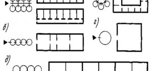
5) smoke and ventilation channels in the internal walls (Figure 5.4);
| Name | Image in scales 1:50 and 1:100 |
| 1.Ventilation shafts and channels | |
| 2. Chimneys (solid fuel) | |
| 3.Smoke pipes (liquid fuel) | |
| 4.Gas exhaust pipes |
Figure 5.4 — Smoke and ventilation channels
6) schematic representation of the staircase (Figure 5.5). The arrow indicates the direction of the march's ascent;
a) lower march, b) intermediate march, c) upper march
Figure 5.5 – Conventional image of stairs on different floors
7) schematic representation of ramps (Figure 5.6). The arrow on the plan indicates the direction of descent;
Figure 5.6 – Conventional image of the ramp on the plan and in the section
conventional graphic designations of elements of sanitary and technical devices in sanitary units (Appendix B, Table B.2);
9) technological equipment for kitchens (stove, work table, sink, refrigerator - at least 2.7 m long and 0.6 m wide) (Appendix C) and the dining area (Appendix D);
10) platforms, mezzanines located above the cutting plane are depicted schematically with a dash-dot thin line with two dots;
11) internal chains of dimensions that determine the dimensions of individual rooms, the connection of walls to coordination axes, the thickness of partitions, the connection and dimensions of doorways and other necessary dimensions;
12) outer chain sizes:
— in the first chain, the dimensions of openings and partitions are located, linking them to the axes;
- the second chain contains the dimensions between the axes of the external and internal walls;
- in the third chain, the size is set between the extreme axes;
Figure 5.7 – Applying external dimensional chains
13) level marks for finished floors located at different levels are indicated in meters with three decimal places separated from the whole number by a comma. Markings of different sections of the floor are placed in meters and enclosed in rectangles with the obligatory indication of the “+” or “–” sign in accordance with Figure 5.8.
Figure 5.8 – Floor level marks on the plan
14) name of the premises, their area. The areas of all rooms are indicated with an accuracy of 0.10 m² and are marked in the lower right corner of the room without the inscription “m²”. The number is underlined with a solid main line.
It is allowed to give the names of the premises and their areas in explication in accordance with GOST 21.501-2011 “Rules for the execution of architectural and construction working drawings”, form 2. In this case, instead of the names of the premises, their numbers are indicated on the plans. For residential buildings, explication of premises, as a rule, is not carried out.
15) cutting lines. Cut lines are usually drawn in such a way that the cut includes stairs, window openings, external and internal doors, and gates. To do this, the cut line is sometimes made as a broken line indicating the turning points on the plan (Figure 5.9).
Figure 5.9 – Building plan
The direction of view for cuts is usually taken from bottom to top and from right to left. The position of the cutting plane is indicated in the drawing by a section line. The design and dimensions of the arrows indicating the direction of view are shown in Figure 5.10.
Figure 5.10 – Drawing of arrows indicating
direction of view
The names of the floor plans of the building indicate the finished floor mark or floor number: Plan at elevation. 0.000; 2nd floor plan.
Sections of the building
The cuts are called longitudinal if the cutting planes are directed along the length of the building, and transverse if the cutting planes are directed perpendicular to the length of the building.
The sections show structures that fall into the cutting plane and are located directly behind this plane. It is allowed to depict not everything that is located behind the section plane, if this is not required to understand the structures of the building. The contour lines of the elements of dissected structures are depicted with a solid thick main line, visible contour lines that do not fall into the section plane are depicted with a solid thin line. It is advisable to highlight supporting structures by shading of materials.
Regardless of how the cut line is drawn, the roof elements are depicted as if the cutting plane is cutting the building along the ridge. In this case, all elements located below the attic floor are depicted based on the actual position of the cutting plane.
The drawings of architectural and structural sections should show:
1) coordination axes of the external and internal walls of the building falling within the cross-section;
2) floor lines of the ground floors, basement, conventional level of the attic floor floor, while the thickness of the attic floor is taken equal to the thickness of the interfloor floor;
3) line of the earth's surface;
4) all structural elements falling into the secant plane or located in close proximity to it, from the foundation to the ridge;
5) window and door openings in external and internal walls (Figure 4.5);
6) staircase design;
7) explanations about the accepted multi-layer structures of floors, floors, roofs and roofs in the form of so-called “flags”, which list the layers of structures indicating the material of each layer and its thickness, but the dimension (mm) is not indicated. Such “flags” can be shown on one of the sections. The second section provides a link to the first, for example
: “Composition of the floor, see section 1−1” (Figure 5.11);
Figure 5.11 – Labels for multilayer structures
the required levels of structures are indicated in meters with three decimal places separated from the whole number by a comma (Figure 5.12).
The conventional “zero” mark accepted for the finished floor level of the first floor is designated “0.000” and is indicated without a sign; marks above zero – with a “+” sign; below zero – with a “–” sign.
Figure 5.12 - Elevations on drawings of sections and facades
9) blind area on plan and section (Figure 5.13)
Figure 5.13 - Blind area
10) schematic representation of ramps (Figure 5.6).
Outside the dimensions of the building sections, two external vertical dimensional chains and one line of numerical marks are applied.
On one vertical dimension line indicate the depth of the foundation, the height of the base, the dimensions of the openings and partitions; on the second - the total height of the above-ground part of the building from ground level to the top of the cornice (parapet).
Numerical marks indicate the levels of the base of the foundation, the surface of the ground, the top and bottom of window openings, the top of door and gate openings, the top of the cornice or parapet, the edges of the overhang and ridge of the roof and other characteristic marks.
Under the section there are horizontal dimension lines indicating the dimensions between the axes of the external and internal walls included in the section and the total distance between the extreme axes, the thickness of the walls and their connection to the axes. Indicates axle markings.
Inside the section drawing, vertical dimension lines are drawn indicating: floor heights, floor thicknesses, doorway heights, window openings heights and distances from the finished floor level to the bottom of the window opening and from the top of the opening to the ceiling. The horizontal dimension lines indicate the thickness of the walls and their relationship to the alignment axes, the thickness of the partitions, the dimensions of the landings and flights of stairs, the dimensions of balconies, loggias, verandas, porches and other elements of the building.
Inside the section, indicate the level of the basement floor, the finished floor levels of all above-ground floors, and the level of the bottom of the load-bearing structure of the attic floor.
Figure 5.14 – Structural section of the building
The names of sections of the building indicate the designation of the corresponding cutting plane on the building plan: Section 1–1; Section A−A.
Floor plan
The floor plan should show:
1) the coordination axes of the building with dimensions that determine the distances between them and the total distance between the extreme axes;
2) contours of external and internal walls without window and door openings, supports (pillars and columns): visible - with a solid thin line, invisible - with a dashed line;
3) smoke and ventilation ducts in the internal walls;
4) the contours of slabs and crossbars with a solid thick main line;
5) monolithic areas;
6) steel anchors (thick main line);
7) marking of floor slabs and anchors (indicating the number of these elements) on the shelves - callouts.
Figure 5.15 – Plan for laying out floor slabs and anchoring slabs (Shereshevsky, Design of civil buildings)
Roof plan
Pitched roofs consist of several intersecting inclined planes - slopes. The roof slopes, intersecting, form dihedral angles. The line where the roof slopes intersect is called a rib. The upper horizontal edge is called the ridge. The intersection of the roof slopes, which are a dihedral angle facing downwards, forms a valley or valley. In one building, all roof slopes usually have the same slope.
When constructing a roof plan drawing, use the following provisions and rules. When the drain line lies in the same horizontal plane and the same angles of inclination of the roof slopes, the following rules are observed:
- if there are two roof slopes with intersecting drain lines, then the projection of the intersection line divides the angle formed by the drain lines in half;
- if there are two roof slopes with parallel drain lines, then the projection of the intersection line is parallel to the drain lines and located at equal distances from them - “ridge”;
- If two intersection lines converge at some point, then, as a rule, a third one comes from it.
To construct a roof plan, the building plan is divided into a number of rectangles. The rectangles should overlap each other, and each side should extend completely or partially beyond the outer contour of the plan, forming a cornice line. Draw an image of the roof above each rectangle, starting with the widest one.
The following is applied to the roof plan (Figure 5.6):
1) extreme and characteristic coordination axes (along the edges of roof sections with various structural and other features) and the distances between them;
2) the outer surface of the outer wall with a dashed line;
3) the cornice line at a distance of about 500 mm from the outer surface of the outer wall;
4) lines of ribs, grooves, ridge;
5) dormer windows and other roof elements;
6) ventilation pipes and chimneys;
7) designations of roof slopes;
height marks of all roof ribs;
9) with external organized drainage - wall gutters and location of drainage funnels.
Figure 5.16 – Example of a roof plan
REQUIREMENTS FOR DRAWINGS
The calculation task must be completed on A3 sheets ( 297x420 mm) in a horizontal position using drawing pencils, black ink or using the AutoCAD graphic editor. When performing architectural and construction drawings, you should be guided by GOST R 21.1101–2013 and GOST 21.501–2011.
A frame is drawn on the sheets , the lines of which are spaced 5 mm from the edge on three sides, and 20 mm on the left side.
The main inscription according to form No. 3 GOST R21.1101–2013 “Basic requirements for design and working documentation”, Appendix G is placed in the lower right corner of the sheet.
Instructions for filling out the specification
The specifications indicate:
a) in the column “Pos.” – positions (brands) of filling elements for window and door openings;
b) in the “Designation” column - GOST designation for windows and doors or an indication of their individual production;
c) in the “Name” column - brands of windows and doors from GOST standards or their sizes in the case of individual production;
d) in the column “Quantity.” – number of elements (not indicated in this calculation task);
e) in the column “Mass, units, kg” - mass in kilograms (not indicated in this calculation task);
f) in the “Note” column - additional information.
Example of filling Specifications for filling window and door openings
| Pos. | Designation | Name | Col. | Unit weight, kg | Note |
| OK1 | GOST 24700-81 | OSP15-9 | |||
| OK2 | GOST 24700-81 | OSB21-13.5 | |||
| OK3 | GOST 24700-81 | OSP21-15 | |||
| OK4 | Ind. order | 900x1200 | Velux roof window | ||
| D1 | GOST 6629-88 | DO24-19U | |||
| D 2 | GOST 6629-88 | DO24-12 | |||
| D3 | GOST 6629-88 | DG21-7L |
5) smoke and ventilation channels in the internal walls (Figure 5.4);
| Name | Image in scales 1:50 and 1:100 |
| 1.Ventilation shafts and channels | |
| 2. Chimneys (solid fuel) | |
| 3.Smoke pipes (liquid fuel) | |
| 4.Gas exhaust pipes |
Figure 5.4 — Smoke and ventilation channels
6) schematic representation of the staircase (Figure 5.5). The arrow indicates the direction of the march's ascent;
a) lower march, b) intermediate march, c) upper march
Figure 5.5 – Conventional image of stairs on different floors
7) schematic representation of ramps (Figure 5.6). The arrow on the plan indicates the direction of descent;
Figure 5.6 – Conventional image of the ramp on the plan and in the section
conventional graphic designations of elements of sanitary and technical devices in sanitary units (Appendix B, Table B.2);
9) technological equipment for kitchens (stove, work table, sink, refrigerator - at least 2.7 m long and 0.6 m wide) (Appendix C) and the dining area (Appendix D);
10) platforms, mezzanines located above the cutting plane are depicted schematically with a dash-dot thin line with two dots;
11) internal chains of dimensions that determine the dimensions of individual rooms, the connection of walls to coordination axes, the thickness of partitions, the connection and dimensions of doorways and other necessary dimensions;
12) outer chain sizes:
— in the first chain, the dimensions of openings and partitions are located, linking them to the axes;
- the second chain contains the dimensions between the axes of the external and internal walls;
- in the third chain, the size is set between the extreme axes;
Figure 5.7 – Applying external dimensional chains
13) level marks for finished floors located at different levels are indicated in meters with three decimal places separated from the whole number by a comma. Markings of different sections of the floor are placed in meters and enclosed in rectangles with the obligatory indication of the “+” or “–” sign in accordance with Figure 5.8.
Figure 5.8 – Floor level marks on the plan
14) name of the premises, their area. The areas of all rooms are indicated with an accuracy of 0.10 m² and are marked in the lower right corner of the room without the inscription “m²”. The number is underlined with a solid main line.
It is allowed to give the names of the premises and their areas in explication in accordance with GOST 21.501-2011 “Rules for the execution of architectural and construction working drawings”, form 2. In this case, instead of the names of the premises, their numbers are indicated on the plans. For residential buildings, explication of premises, as a rule, is not carried out.
15) cutting lines. Cut lines are usually drawn in such a way that the cut includes stairs, window openings, external and internal doors, and gates. To do this, the cut line is sometimes made as a broken line indicating the turning points on the plan (Figure 5.9).
Figure 5.9 – Building plan
The direction of view for cuts is usually taken from bottom to top and from right to left. The position of the cutting plane is indicated in the drawing by a section line. The design and dimensions of the arrows indicating the direction of view are shown in Figure 5.10.
Figure 5.10 – Drawing of arrows indicating
direction of view
The names of the floor plans of the building indicate the finished floor mark or floor number: Plan at elevation. 0.000; 2nd floor plan.
Sections of the building
The cuts are called longitudinal if the cutting planes are directed along the length of the building, and transverse if the cutting planes are directed perpendicular to the length of the building.
The sections show structures that fall into the cutting plane and are located directly behind this plane. It is allowed to depict not everything that is located behind the section plane, if this is not required to understand the structures of the building. The contour lines of the elements of dissected structures are depicted with a solid thick main line, visible contour lines that do not fall into the section plane are depicted with a solid thin line. It is advisable to highlight supporting structures by shading of materials.
Regardless of how the cut line is drawn, the roof elements are depicted as if the cutting plane is cutting the building along the ridge. In this case, all elements located below the attic floor are depicted based on the actual position of the cutting plane.
The drawings of architectural and structural sections should show:
1) coordination axes of the external and internal walls of the building falling within the cross-section;
2) floor lines of the ground floors, basement, conventional level of the attic floor floor, while the thickness of the attic floor is taken equal to the thickness of the interfloor floor;
3) line of the earth's surface;
4) all structural elements falling into the secant plane or located in close proximity to it, from the foundation to the ridge;
5) window and door openings in external and internal walls (Figure 4.5);
6) staircase design;
7) explanations about the accepted multi-layer structures of floors, floors, roofs and roofs in the form of so-called “flags”, which list the layers of structures indicating the material of each layer and its thickness, but the dimension (mm) is not indicated. Such “flags” can be shown on one of the sections. The second section provides a link to the first, for example
: “Composition of the floor, see section 1−1” (Figure 5.11);
Figure 5.11 – Labels for multilayer structures
the required levels of structures are indicated in meters with three decimal places separated from the whole number by a comma (Figure 5.12).
The conventional “zero” mark accepted for the finished floor level of the first floor is designated “0.000” and is indicated without a sign; marks above zero – with a “+” sign; below zero – with a “–” sign.
Figure 5.12 - Elevations on drawings of sections and facades
9) blind area on plan and section (Figure 5.13)
Figure 5.13 - Blind area
10) schematic representation of ramps (Figure 5.6).
Outside the dimensions of the building sections, two external vertical dimensional chains and one line of numerical marks are applied.
On one vertical dimension line indicate the depth of the foundation, the height of the base, the dimensions of the openings and partitions; on the second - the total height of the above-ground part of the building from ground level to the top of the cornice (parapet).
Numerical marks indicate the levels of the base of the foundation, the surface of the ground, the top and bottom of window openings, the top of door and gate openings, the top of the cornice or parapet, the edges of the overhang and ridge of the roof and other characteristic marks.
Under the section there are horizontal dimension lines indicating the dimensions between the axes of the external and internal walls included in the section and the total distance between the extreme axes, the thickness of the walls and their connection to the axes. Indicates axle markings.
Inside the section drawing, vertical dimension lines are drawn indicating: floor heights, floor thicknesses, doorway heights, window openings heights and distances from the finished floor level to the bottom of the window opening and from the top of the opening to the ceiling. The horizontal dimension lines indicate the thickness of the walls and their relationship to the alignment axes, the thickness of the partitions, the dimensions of the landings and flights of stairs, the dimensions of balconies, loggias, verandas, porches and other elements of the building.
Inside the section, indicate the level of the basement floor, the finished floor levels of all above-ground floors, and the level of the bottom of the load-bearing structure of the attic floor.
Figure 5.14 – Structural section of the building
The names of sections of the building indicate the designation of the corresponding cutting plane on the building plan: Section 1–1; Section A−A.
Floor plan
The floor plan should show:
1) the coordination axes of the building with dimensions that determine the distances between them and the total distance between the extreme axes;
2) contours of external and internal walls without window and door openings, supports (pillars and columns): visible - with a solid thin line, invisible - with a dashed line;
3) smoke and ventilation ducts in the internal walls;
4) the contours of slabs and crossbars with a solid thick main line;
5) monolithic areas;
6) steel anchors (thick main line);
7) marking of floor slabs and anchors (indicating the number of these elements) on the shelves - callouts.
Figure 5.15 – Plan for laying out floor slabs and anchoring slabs (Shereshevsky, Design of civil buildings)
Roof plan
Pitched roofs consist of several intersecting inclined planes - slopes. The roof slopes, intersecting, form dihedral angles. The line where the roof slopes intersect is called a rib. The upper horizontal edge is called the ridge. The intersection of the roof slopes, which are a dihedral angle facing downwards, forms a valley or valley. In one building, all roof slopes usually have the same slope.
When constructing a roof plan drawing, use the following provisions and rules. When the drain line lies in the same horizontal plane and the same angles of inclination of the roof slopes, the following rules are observed:
- if there are two roof slopes with intersecting drain lines, then the projection of the intersection line divides the angle formed by the drain lines in half;
- if there are two roof slopes with parallel drain lines, then the projection of the intersection line is parallel to the drain lines and located at equal distances from them - “ridge”;
- If two intersection lines converge at some point, then, as a rule, a third one comes from it.
To construct a roof plan, the building plan is divided into a number of rectangles. The rectangles should overlap each other, and each side should extend completely or partially beyond the outer contour of the plan, forming a cornice line. Draw an image of the roof above each rectangle, starting with the widest one.
The following is applied to the roof plan (Figure 5.6):
1) extreme and characteristic coordination axes (along the edges of roof sections with various structural and other features) and the distances between them;
2) the outer surface of the outer wall with a dashed line;
3) the cornice line at a distance of about 500 mm from the outer surface of the outer wall;
4) lines of ribs, grooves, ridge;
5) dormer windows and other roof elements;
6) ventilation pipes and chimneys;
7) designations of roof slopes;
height marks of all roof ribs;
9) with external organized drainage - wall gutters and location of drainage funnels.
Figure 5.16 – Example of a roof plan
REQUIREMENTS FOR DRAWINGS
The calculation task must be completed on A3 sheets ( 297x420 mm) in a horizontal position using drawing pencils, black ink or using the AutoCAD graphic editor. When performing architectural and construction drawings, you should be guided by GOST R 21.1101–2013 and GOST 21.501–2011.
A frame is drawn on the sheets , the lines of which are spaced 5 mm from the edge on three sides, and 20 mm on the left side.
The main inscription according to form No. 3 GOST R21.1101–2013 “Basic requirements for design and working documentation”, Appendix G is placed in the lower right corner of the sheet.
Specification of elements for filling doorways: GOST requirements
During the construction of any type of building, one of the main documents establishing the design plan is the specification form for the elements of filling the openings. It indicates a list of necessary items, their design features, sizes and other characteristics. There are even separate GOST standards on this subject; they primarily concern the rules for drawing up specifications and the principle of submitting the necessary information.
What it is
For a person who has heard such a term for the first time, it will be interesting to find out in more detail what the specification of elements for filling doorways is. At its core, it is a kind of document, or rather, part of the design documentation for any building. It complements the drawn up drawings and demonstrates the names and models of those elements with which it is planned to fill the doorways in the future. In other words, it is a list of structures and their individual parts that are required to complete a construction project. Thanks to the specification, you can estimate the construction budget and see a more accurate plan for the final result.
When performing independent work on the construction of a building on a private plot, there is no need to draw up a specification. You can make do with approximate calculations and purchase everything you need during the interior finishing work.
The rules for compiling this list are determined by GOST. The same requirements also apply to the specifications for window openings, niches and partitions with gaps.
Specification of openings with door opening type
What documents need to be drawn up?
The designer draws up a number of papers to provide to control services.
Among them:
- technological maps;
- SOKK - operational quality control schemes (drawn up for all work performed);
- SNiP "Organization, production, acceptance of work."
Using these documents, the inspector carries out control:
- quality of materials, consumption;
- location of all building parts according to the drawings;
- compliance of preliminary calculations with reality.
SOCC consists of 4 parts:
- List of controlled operations. The document also defines the control method and appoints the person responsible for this procedure.
- Technical requirements applicable to a number of construction and installation works; list of acceptable deviations according to standards.
- The procedure for carrying out all work and the requirements that must be observed.
- Requirements for materials, products and their parts, quality, characteristics with reference to GOST clauses.
General requirements according to GOST
In order for the specification form for opening filling elements to comply with GOST, it is necessary to carefully study standard number 21.101. This describes general provisions regarding the rules for implementing design documentation during the construction of a building. It is imperative to draw up detailed drawings, which should be accompanied by a specification. The corresponding designations allow you to more accurately present a picture of the future structure.
You should also refer to GOST 21.501. This paragraph explains the rules for drawing up the drawings themselves. Both standards contain many subclauses. As for the doorways themselves, they are mentioned here separately. When performing specifications on drawings, it is important to comply with special requirements regarding the dimensions of the table. Specific dimensions for columns and spacing for rows are provided here.
In general, for a person who does not have special skills or education in this field, it will be quite difficult in a short time to understand all the intricacies of drawing up project documentation, including specifications.
GOST 21.501 - a document regulating the rules for drawing up specifications
What to include in the diagram
According to GOST, there is a pre-designed form intended for filling out the specification. It takes into account the presence of all the necessary columns for entering product parameters. There is a category of mandatory names that cannot be removed from the form. In some cases, they are quite sufficient for a basic description of the situation. If you need to indicate any specific data, it is possible to add auxiliary columns for this type of information.
In general, the following parameters are entered into the diagram:
- item number;
- product name;
- number of units.
Additionally, specific units of measurement, the weight of items recorded in the specification, or a specific brand or model may be indicated.
For doorways, the specification list usually includes only a few components. First of all, this is, of course, the door leaf and frame or arch. In addition, additional elements, thresholds and platbands, as well as other elements of the design of the opening, can be attributed to them. In some cases, the inventory also contains individual fragments of the canvas itself. For example, it could be glass and stained glass. Protective structures such as grilles and roller shutters must also be recorded on the form.
An example of a door specification in accordance with GOST
How to determine what width the door leaf should be installed
If the doors are simply being replaced, the easiest way is to measure the door that is already in place. You definitely can't go wrong. If you are installing doors for the first time, you need to measure the doorway and select an option that will require minimal effort during installation.
The width of the interior door frame depends on the existing opening
How to measure a doorway
To choose the correct size of a door or door block, you need to know the exact dimensions of the opening in which they will be installed. Measurements are carried out using a regular construction tape. We measure any parameter at least at two points. If the difference is visually visible, you can measure more times, adjusting the position of the tape measure at your discretion.
To make sure that the size of the doorway is standard, take a tape measure and measure the actual parameters of the passage
The height of the doorway is measured at one and the other jamb, the width at the top and bottom, approximately at a distance of 30-50 cm from the floor and lintel. You can also take measurements in the middle of the height. You also need to measure the thickness of the opening (wall thickness). It must be checked at least at two points on each side.
We record all measurements. It is better to do this on a diagram of the doorway. If there are deviations, we look at how serious the situation is and whether it can be corrected. If the “narrowest” place corresponds to the smallest possible standard opening, you can leave everything as is. Otherwise, you will have to try to correct the situation. It is already described above how.
You need to check the geometry of the opening. Otherwise there will be difficulties during installation
But size isn't everything. It is necessary to check whether there are any deviations in geometry. The side walls of doorways should be vertical, and the lintel should be horizontal. You can check the correctness of the shape using a regular building level (bubble level), but it is more convenient and more accurate to use a level. You can check the side walls with a regular plumb line. If the deviations are large, they need to be corrected. If their size is within a centimeter, it will be possible to compensate during installation using mounting plates and construction foam.
Note box
In addition to the main provisions, GOST requires the presence of an additional column in the specification form - “Notes”. In this section, brief notes can be made regarding important design points that are not included in the general list of columns. These primarily include:
- door dimensions;
- dimensions of the opening framing structure;
- the material from which the filling element is made;
- cost of goods;
- total weight.
In addition to the specification, ideally there should be a detailed building plan with drawings in several projections. The rules for their implementation are also established by GOST.
The specification allows you to more fully cover the list of upcoming work and indicates a list of necessary materials to complete construction and design openings. This is very convenient when you need to provide an estimate for each item.
Entrance door standards
The size of the opening for the front door is slightly different from the internal options. More precisely, existing standards apply in high-rise buildings, but in private construction, owners prefer to arrange openings according to their own ideas about practicality.
If we look in detail, the standards here are not very different from internal ones, so the entrance door should have a height of 2000 to 2300 mm. The width of the entrance door is calculated based on a minimum leaf width of 900 mm, with the exception of wooden panels, the width of which can reach 800 mm.
Don’t forget that in addition to city apartments and private houses, doors also need entrances to entrances, shops, office buildings, and so on. The width of the opening is calculated taking into account fire safety rules, but in any case it is made larger than the domestic standard of 900 mm.
For both metal and wooden structures, the opening must correspond to the width of the selected door.
In cases where single-leaf entrance doors for some reason do not become obsolete, double or one-and-a-half structures are installed at the entrance. With doubles, everything is simple; the adjacent canvases are the same width. In one-and-a-half gates, the main leaf has a width of 800-900 mm, and the auxiliary leaf has various standard sizes.